background image

14

Installation of table-top type table

Mount the sewing machine as shown in Figure 6 and 7.

Fix the table with screws and nuts.  Place the rubber cushion on the bolt and then fix the oilpan onto the cushion securely.

Mount the sewing machine as illustrated in Figure 8 and 9.

First, insert the screw into the bed support bar 

and fix it onto the table.  Then fit the rubber cushion onto the screw and

place the oilpan securely. 

Installation of semi-submerged type table

[ Figure 7 ]

[ Figure 6 ]

Machine

Oilpan

Table

Table

[ Figure 9 ]

[ Figure 8 ]

Machine

Oilpan

② ⑩

Table

Table

4mm

Содержание SS-7350 Series

Страница 1: ...AD THIS MANUAL BEFORE STARTING USE 2 KEEP THIS MANUAL IN SAFE PLACE FOR REFERENCE WHEN THE MACHINE BREAKS DOWN M MM ME E 0 09 90 09 92 29 9 USER S MANUAL R S Su un nS St ta ar r C CO O L LT TD D SS 7350 Series Small cylinder bed interlock sewing machine ...

Страница 2: ...e powerful operation enhanced durability and more sophisticated design to meet a number of user s needs 2 Please read this user s manual thoroughly before using the machine Make sure to properly use the machine to enjoy its full performance 3 The specifications of the machine are subject to change aimed to enhance product performance without prior notice 4 This product is designed manufactured and...

Страница 3: ...d With Top Cover Thread Top Cover Thread G L S For Medium Weight Fabrics For Light Weight Fabrics For Special Specifications Shape of Stitch Plate 48 56 64 Needle Space 3 2mm 4 0mm 4 8mm UT A UT B ST C Lower Thread Trimming Air Pressure 2 Lower Thread Trimming Air Pressure 3 Upper Thread Trimming Cylinder Bed Option Device HE WK1 ATF TL PK Hemming Guide Walking Presser Foot Tape Feeder Side meter ...

Страница 4: ...10 4 Installation 11 1 Installation of table 11 2 Installation of motor and belt 15 3 Adjustment of belt tension 16 4 Installation of belt cover 16 5 Installing cover for needle bar thread guide 17 6 Installation of thread guide plate 17 5 Sewing speed and rotating direction of pulley 18 6 Lubrication 18 1 Lubricating oil 18 2 Supplying oil 19 3 Oil Gauge and Oil Window 19 4 Oil change 19 5 Cleani...

Страница 5: ...hine 27 1 Adjustment of needle thread tension 27 2 Adjustment of looper thread tension 29 3 Adjustment of needle and spreader 29 4 Adjustment of needle and looper timing 31 5 Adjusting the feed dog height 32 6 Adjusting needle and needle plate 32 7 Presser foot separation and lift volume 36 9 Automatic Thread Trimmer 37 1 Operation 37 2 Wiring 39 3 Air pressure wiring map 44 4 Installation of sync...

Страница 6: ...ompletely out of power ⓑ Not any of the machine specifications or parts should be changed without consulting the company Such changes may make the operation dangerous ⓒ Spare parts produced by the company should only be used for replacements ⓓ Put all the safety covers back on the machine after the machine has been repaired The machine may not work properly or breakdown if installed in certain pla...

Страница 7: ...ore threading the needle or checking after work ⓗ Do not step on the pedal when turning the power on ⓘ Do not operate the machine with any cooling fan blocked The air filter on control box must be cleaned once a week ⓙ If possible install the machine away from source of strong electrical noise such as high frequency welding machines 4 Operating machine Warning Caution 5 Safety devices ⓐ Safety lab...

Страница 8: ...ut finger guard and safety devices Before threading changing and needle cleaning etc switch off main switch 손가락 보호대와 안전장치 없이 작동하지 마십시오 실 바늘교환시나 청소전에는 반드시 주전원의 스위치를 꺼 주십시오 CAUTION 주 의 Do not operate without finger guard and safety devices Before threading changing and needle cleaning etc switch off main switch 손가락 보호대와 안전장치 없이 작동하지 마 십시오 실 바 늘 교 환 시 나 청 소 전 에 는 반 드 시 주전원의 스위치를 꺼 주십시오 CAUTION 경 고 CA...

Страница 9: ...ting cylinder Upper shaft pulley Thread adjusting device Oil gauge Main feed adjusting screw Main feed adjusting lever Presser foot Air wiper Power switch Bobbin stand Safety devices Thread guide cover for needle thread Thread take up lever cover for needle thread Finger guard 21 Safety plate 21 ...

Страница 10: ...ine ISO 406 407 602 605 General seaming of knitted materials T shirt collar children clothes sleeves Max 4 500 s p m 1 4 4 2mm Stitches per inch 6 18 The number of stitches per 30mm 7 21 UY 128GAS No 65 No 90 Standard No 70 3 needle 4 8 5 6 6 4 mm 33mm Max 7 mm 5 mm if equipped with a spreader Adjusting lever method Max Normal Differential Ratio 1 1 4 Max Reverse Differential Ratio 1 0 8 adjusting...

Страница 11: ... 3 K 280 Section K K Scale 1 2 72 5 75 540 25 10 C 1 C 1 C 1 C 1 80 60 40 1 Installation of table Types of table A Table Top Type trimming Figure 2 275 다리 장착 위치 Stand Mounting Position 805 다리 장착 위치 Stand Mounting Position 75 120 75 ф17 Hole thru ф25 K 57 0 3 159 0 5 180 0 5 80 60 40 360 255 4 R20 100 685 3 ф9 Hole thru 66 0 3 33 0 3 140 1 200 70 235 0 5 47 5 0 3 K 280 4 ф7 Hole thru ф40 72 5 225 3...

Страница 12: ...0 75 Stand Mounting Position Section K K Scale 1 2 C 1 C 1 C 1 C 1 75 1 200 C Semi Submerged Type Trimming type Figure 4 다리 장착 위치 Stand Mounting Position 다리 장착 위치 Stand Mounting Position 120 C 1 C 1 159 0 5 805 275 80 360 100 4 R20 1 200 280 75 235 0 5 Section K K Scale 1 2 3 60 4 ф13 265 4 ф25 5 280 0 5 6 4 ф50 8 R 5 3 R 1 0 ф17 Hole thru 4 ф13 Hole thru 3 ф9 Hole thru 66 0 3 33 0 3 4 ф25 5 B Dep...

Страница 13: ...13 Figure 5 E Options for small sized motor type ...

Страница 14: ... the oilpan onto the cushion securely Mount the sewing machine as illustrated in Figure 8 and 9 First insert the screw into the bed support bar and fix it onto the table Then fit the rubber cushion onto the screw and place the oilpan securely Installation of semi submerged type table Figure 7 Figure 6 Machine Oilpan Table Table Figure 9 Figure 8 Machine Oilpan Table Table 4mm ...

Страница 15: ...ith each other Mount the sewing machine as shown in Figure 10 and 11 Insert the screw and nut into the table and place the rubber cushion on the bolt Securely place the oilpan on the cushion afterwards The diameter of pulleys in the market is generally set with a 5 mm clearance 75 80 85 90 100 110 120 130 s p m of machine 50Hz 60Hz 3 200 3 900 3 400 4 100 3 600 4 400 3 900 4 700 4 300 5 200 4 700 ...

Страница 16: ...ts center portion is pushed with a finger Refer to figure 13 Figure 13 Fasten the belt cover upper with a screw as shown in figure 14 For A Type table mount the belt cover lower as shown in figure 15 10 20mm Be sure to turn the power switch off before adjusting belt tension Warning Always install the belt cover for safety Warning Figure 15 Figure 14 ...

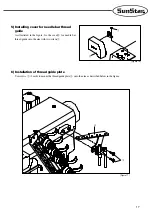
Страница 17: ...As illustrated in the figure fix the cover for needle bar thread guide onto the arm with two screws 6 Installation of thread guide plate Use screws 2 each to mount the thread guide plate onto the arm as described below in the figure Figure 17 Figure 16 ...

Страница 18: ...ction of the lower shaft pulley and upper shaft pulley is clockwise Figure 18 1 Lubricating oil Use industrial purpose lubricating oil supplied by SunStar or SF oil by YANASE for this particular type of sewing machine Sewing speed and rotating direction of pulley 5 5 6 6 Lubrication Be sure to turn the power switch off before oiling Warning Do not put foreign materials into the lubricating oil It ...

Страница 19: ...et out the lubricating oil Fasten oil discharge screw securely afterwards Return the sewing machine back to the original location Place the V belt on the motor pulley Refer to 2 Supplying oil for lubrication The sewing machine is not oiled when shipped out from the factory To ensure trouble free use of the sewing machine open the upper rubber lid and supply oil to the upper line of the oil gauge 2...

Страница 20: ...y if dust gets built up in oil filter Check the oil filter once every six months Check the oil filter through the oil window if there is no or only little amount of oil being supplied Before checking the oil filter remove the oil filter cover Clean dust build ups inside the oil filter When removing the oil filter cover be sure to prevent the remaining oil in the oil filter from leaking Caution Whe...

Страница 21: ...er Then fasten the screw firmly Figure 26 27 Figure 25 1 Needle used This sewing machine uses UY128GAS needles Needles come in various size Select the most appropriate needle depending on the thickness or the type of sewing materials Japanese size 9 10 11 12 13 14 Metric size 65 70 75 80 85 90 Figure 27 Figure 26 7 7 Standard adjustments of the sewing machine Turn the power switch off before insta...

Страница 22: ...or the second needle thread in the case of 2 needle sewing machine refer to the above instructions for threading 4 Adjustment of thread tension Thread tension must be adjusted according to the type of threads and fabrics stitch length and other sewing conditions Thread tension can be adjusted by rotating the thread adjusting device cap Turn clockwise to strengthen and counterclockwise to weaken th...

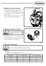
Страница 23: ...th can be adjusted straight from 1 4mm to 4 2 mm The table below shows stitch length number of stitches per inch 25 4mm and per 30 mm Stitch length mm No of stitches per inch No of stitches per 30mm 4 2 6 7 5 3 6 7 8 2 4 10 5 12 5 1 4 18 21 6 Adjustment of presser foot position After unfastening the screw move the front part of the presser foot left and right to bring the needle to pass the center...

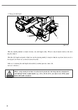
Страница 24: ...is turned within the scope from the lever scale to the stopper fix the lever at a certain location with a nut In the case of adjusting the stitch length in the middle of machine operation connect the hook etc to the lever When using sewing machines mounted with pneumatic trimming devices designed to automatically find the needle location e g UT A UT B or ST C be sure to turn off the power before s...

Страница 25: ...ownward the reverse differential feed is possible When the punched mark of the differential feed lever is matched with the center of the fixing screw the differential ratio becomes 1 1 Be sure to turn the power switch off before adjusting differential feed Warning When the stitch length is 4 2mm the maximum differential ratio is 1 1 2 Caution Figure 33 ...

Страница 26: ...e needle cooling device and needle thread lubricating device as a standard option Figure 35 Figure 34 Be sure to turn the power switch off before work Warning Open cover of the silicon oiling tank and cover of the needle thread oiling tank to check the level of silicon oil Oil if necessary If there is no need for silicon due to specific sewing conditions remove the felt to prevent the needle and t...

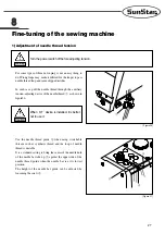
Страница 27: ... needle thread guide when using stretchable threads such as synthetic thread and the loop of needle thread is unstable It is a standard setting to bring the center of the needle hole of the needle bar take up against the upper side of the needle thread guide when the needle bar is at its lowest position The height of the needle bar guide can be adjusted by loosening the screw 8 8 Fine tuning of th...

Страница 28: ...and to loosen thread move it in the X direction The thread take up lever can be adjusted after loosening If the adjustment is not enough loosen the fixing screw and move thread path adjusting the thread tension Thread is tightened when it is moved in the Y direction and it is loosened when it is moved in the Y direction Fix the top of thread path at 18mm away from the center of the fixing screw Fi...

Страница 29: ...er moves to the left the clearance between the left needle and the hook tip of the spreader a is 0 5mm 0 8mm Figure 41 When the spreader sits at the far left the distance from the left needle center to the hook tip of the spreader a is 4 5mm 5 5mm The height between the stitch plate and the lower side of the spreader is 8 5mm 9 5mm Figure 42 The spreader can be adjusted by untightening the spreade...

Страница 30: ... thread eyelet is 1 0mm Bring the needle groove of top cover thread eyelet to the centerline of the slots of the top cover thread guide Tighten the screw afterwards Adjust 1 2 and 3 depending on the type of thread used Figure 45 0 5mm 1 0mm Adjusting decorative thread The lifting of decorative thread eyelet right in the Y direction reduces thread supply and the lowering of the eyelet in the Y dire...

Страница 31: ... makes it easy to adjust the left and right position of the loopers Timing Gauge is an optional part If needed you may ask for the purchase to where the product was bought or SunStar directly Use Timing Gauge Timing Gauge is marked with such scales as A B C D and E depending on needle distance When the looper is in the most right end position and the right needle settles on the V groove according ...

Страница 32: ...le of 2 and the height are determined Location of looper cam The figure shows the looper cam view from the needle bar direction Lower the needle from the highest point When the needle reaches the half point of the looper loosen the fixing screw to escape the thread from the highest position of the looper cam Figure 50 Figure 51 Figure 52 1 2 ...

Страница 33: ...f the needles along the line of the needle guard R 0 2 0 3mm For 3 needle type For 2 needle type 0 2 0 3mm Figure 56 Needle height When the end tip of the looper passes the left needle center it must pass the needle groove at 0 5 1 0 mm off from the upper part In other words the height of the needle is set by the looper Using a driver unfasten the screw of the needle bar holder through a hole in t...

Страница 34: ...edle set the clearance with the needle guard F at 0 0 3 mm Adjustments can be done by untightening th screws Front rear position of needle guard R When the end tip of the looper comes to the center of the right needle press the needle guard R to adjust the clearance between the needle and the looper at 0 0 05 mm At this point be sure to set the distance between the left needle and the needle guard...

Страница 35: ...and adjust the distance from the needle plate face to the feed dog face at 1 1 2mm Adjustment can be conducted after loosening the fixing screws 6 Adjusting needle and needle plate When adjusting the needle bar height the needle should be aligned horizontally with high accuracy like the solid line in the figure It should not be aligned as the dotted line in the figure Figure 62 Figure 63 1 0mm 1 2...

Страница 36: ...ver and set the distance between the needle plate face and the presser foot bottom at 5 0mm in the case of using decorative thread looper and then fasten the fixing screw for the knee lift lever stopper Then set the distance between the presser bar bushing bottom and the presser bar collar face at 0 2mm and fasten the fixing screw The distance will be 7mm when there is no spreader However without ...

Страница 37: ... begin to move under the needle plate to cut the needle thread and looper thread The looper thread will be caught by clamp spring and air wiper will run for two seconds and then presser foot will go up For UT A device lifting of the presser foot and wiper operation will begin at the same time D Leave the pedal at neutral The presser foot will go down 1 Operation Figure 67 Start Neutral Trimming Pr...

Страница 38: ...gin to move under the needle plate to cut the needle thread and looper thread The clamp spring will catch the looper thread after trimming top cover thread and the presser foot will go up D Leave the pedal at neutral The presser foot will go down 2 Operation procedures for ST C device Figure 68 Start Neutral Trimming Presser foot lifting Be sure to place sewing materials under the presser foot bef...

Страница 39: ...s original position adjust so that the switch is turned on c Fix screws and 2 Wiring 1 Limit switch Figure 69 B Connecting limit switch a General Servo motor A Fortuna Ⅲ Link the limit switch cord to the 12P connector as follows Figure 70 White White Black Black Switch and lamp connector White Black Switch and lamp connector b Small motor A Fortuna Ⅳ Link the limit switch cord to 8P connector as f...

Страница 40: ... will not work if the cords are plugged in incorrectly to opposite power 2 Connecting solenoid valve A Fortuna Ⅲ servo motor Figure 72 Standard solenoid connector Knee lifting solenoid connector Green Figure 73 Standard solenoid connector Knee lifting solenoid connector Green Solenoid valve number Solenoid valve application Connector type Pin number 1 Presser foot lifting Knee lifting solenoid con...

Страница 41: ...d valve carries polarity check the connection between the cable and the connector The device will not work if the cords are plugged in incorrectly to opposite power Solenoid valve number Solenoid valve application Connector type Pin number 1 Presser foot lifting Knee lifting solenoid connector 3 4 signal 2 Lower trimming Standard solenoid connector 2 signal 6 3 Top cover thread trimming Standard s...

Страница 42: ...ion between the cable and the connector The device will not work if the cords are plugged in incorrectly to opposite power B Fortuna Ⅳ Compact Servo Motor Figure 75 Standard solenoid connector Figure 76 Standard solenoid connector Solenoid valve number Solenoid valve application Connector type Pin number 1 Presser foot lifting Standard solenoid connector 2 10 signal 2 Lower trimming Standard solen...

Страница 43: ...arity check the connection between the cable and the connector The device will not work if the cords are plugged in incorrectly to opposite power Solenoid valve number Solenoid valve application Connector type Pin number 1 Presser foot lifting Standard solenoid connector 2 10 signal 2 Lower trimming Standard solenoid connector 11 signal 3 3 Top cover thread trimming Standard solenoid connector 12 ...

Страница 44: ...44 3 Air pressure wiring map 1 UT B device Figure 78 2 5 4 350mm 2 5 4 400mm 2 5 4 150mm 2 5 4 300mm 2 5 4 300mm 4 6 1 500mm solenoid valve air pressure 0 35MPa 0 45MPa 4Kgf cm2 5Kgf cm2 IN OUT ...

Страница 45: ...45 2 UT A device Figure 79 2 5 4 150mm IN OUT 2 5 4 200mm 2 5 4 200mm 2 5 4 150mm 2 5 4 300mm 2 5 4 300mm 4 6 1 500mm solenoid valve air pressure 0 35MPa 0 45MPa 4Kgf cm2 5Kgf cm2 ...

Страница 46: ...46 3 ST C device Figure 80 2 5 4 350mm 2 5 4 600mm 2 5 4 580mm 2 5 4 300mm 2 5 4 300mm 4 6 1 500mm solenoid valve air pressure 0 35MPa 0 45MPa 4Kgf cm2 5Kgf cm2 ...

Страница 47: ...changed 4 Installation of synchronizer sensor Figure 81 6 To see whether the needle bar is located at 0 5mm below the highest point press the pedal and run the machine Figure 82 Leave the trimming cylinder plug pulled off from the control box in the motor Otherwise parts can be damaged Warning 1 At this point the needle bar should be positioned at the highest point 2 The optimal condition for the ...

Страница 48: ...3 Adjustment between moving blade and fixed blade Figure 85 Before adjustments always turn off the motor switch and check to make sure that the motor is in stop mode Warning The trimming device can be moved manually only when the needle is at the highest point Otherwise parts can be damaged Warning Figure 84 0 5mm 1 Adjusting thread trimming air cylinder A The desirable stroke is 25mm B Adjust the...

Страница 49: ...essure and the end tip of the fixed blade G Fix the screw tightly 4 Position of clamp spring and clamp spring pressure Figure 86 2mm 2mm Figure 87 A The looper thread is caught by the clamp spring after trimming B To increase pressure turn the screw clockwise and to decrease pressure turn it counter clockwise 5 Pressure adjustment of clamp spring Before adjustments always turn off the motor switch...

Страница 50: ...of fixed blade body A Unfasten the screw B Set a clearance of 1mm between the left end tip of the thread trimming base and the left end tip of the stopper for fixed blade body C Adjust the screw afterwards Before adjustments always turn off the motor switch and check to make sure that the motor is in stop mode Warning Do not force the fixed blade body to the left for the clamp spring pressure can ...

Страница 51: ...ft and right to set a clearance of 3 5mm 4 5mm between the needle thread hook and the left needle D Fasten the nut afterwards 7 Relation between moving blade and needle Figure 90 3 5mm 4 5mm Needle Before adjustments always turn off the motor switch and check to make sure that the motor is in stop mode Warning Figure 89 21 ...

Страница 52: ...ter of the looper C To move the endpoint 22 back loosen the screw 23 to turn the hinge R for blade guide lever 24 clockwise To move the endpoint 22 front turn the hinge counter clockwise D Fasten the screw 23 afterwards 8 Position of moving blade point Figure 91 22 12mm Before adjustments always turn off the motor switch and check to make sure that the motor is in stop mode Warning Figure 92 23 24...

Страница 53: ...hen the moving blade body stops as described above adjust the clearance between the moving blade body and the moving blade carrier guide upper 28 between 0 05 and 0 1mm C Tighten the screws 27 9 Adjusting moving blade carrier guide upper Figure 93 Before adjustments always turn off the motor switch and check to make sure that the motor is in stop mode Warning 28 27 28 0 05mm 0 1mm ...

Страница 54: ...Does the needle thread get pulled by the hook to ensure trimming by the fixed blade D Does the looper thread get pulled by the hook to ensure trimming by the fixed blade 10 Relation between needle thread looper thread and moving blade Figure 94 30 29 Figure 95 Before adjustments always turn off the motor switch and check to make sure that the motor is in stop mode Warning ...

Страница 55: ...tch guide 6 Adjustment of thread tension release mechanism Figure 97 A Loosen the nut of the thread trimming air cylinder B Adjust the holder for limit switch bracket to bring the thread tension release connecting plate to come between the screw head and the tension release lever C Tighten the nut 2 Thread tension release connecting plate Before adjustments always turn off the motor switch and che...

Страница 56: ...usting lever Cylinder T shirt collar children clothes sleeves Adjusting lever method adjusting screw method 4 Releasing looper thread Figure 98 A Loosen the screw of the tension release lever located on the backside of the machine B Lift the thread pull off lever to the top C Tighten the screw afterwards 3 Thread pull off lever Figure 99 ...

Страница 57: ...ff bar and the top of the guide for thread pull off bar D With the screw fix the thread pull off bar onto the thread pull off bar holder E Loosen the screw F Set a clearance of 4 0mm between the collar for thread pull off bar and the guide for thread pull off bar G Fasten the screw 5 Tension disc separator Figure 100 21 22 23 35mm 4mm Before adjustments always turn off the motor switch and check t...

Страница 58: ...hread pull off hook unit Figure 101 35mm 4mm 21 22 23 Before adjustments always turn off the motor switch and check to make sure that the motor is in stop mode Warning A Use the thread pull off hook B unit 23 only when you are using wool thread for the looper thread When the thread pull off hook B unit 23 is not in use bring it up so that thread does not get caught B Do not force the thread pull o...

Страница 59: ... the amount of air with the speed controller To reduce the air turn the screw clockwise and to increase turn it counter clockwise 7 Adjustment of air wiper Figure 102 1mm 2mm Figure 103 IN OUT Before adjustments always turn off the motor switch and check to make sure that the motor is in stop mode Warning A Keep the air level to the minimum as long as the machine functions well B If air gets out f...

Страница 60: ...t point turn the knuckle for knee lifting air cylinder to bring up the presser foot by 5mm 7mm 3 Fasten the nut afterwards 8 Presser foot lifter mechanism Figure 104 Before adjustments always turn off the motor switch and check to make sure that the motor is in stop mode Warning ...

Страница 61: ...plate stitch plate and the blade tip of the movable trimming knife D After adjustments fix the screws and E Move the movable trimming knife up and down to see whether it crosses top cover thread 9 ST C device Figure 105 Figure 106 Needle plate 5 5mm 6mm Figure 107 Top cover thread Before adjustments always turn off the motor switch and check to make sure that the motor is in stop mode Warning Loos...

Страница 62: ...e and vice versa Figure 108 Speed controller 3 Clearance between movable trimming knife and fixed trimming knife The clearance between the movable trimming knife and the fixed trimming knife before the blades move is 0 0 5mm Figure 109 0 0 5mm Before adjustments always turn off the motor switch and check to make sure that the motor is in stop mode Warning The stroke of the movable trimming knife i...

Страница 63: ... shorten the thread after trimming lift the thread pull off hook up and vice versa 5 Adjusting thread pull off hook unit 4 Pressure of thread clamp spring Figure 110 Figure 111 Before adjustments always turn off the motor switch and check to make sure that the motor is in stop mode Warning A Use as much thread stroke as possible If there is not enough stroke trimming thread may not be caught after...

Отзывы: