


14
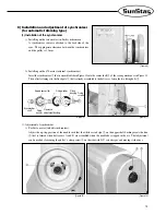
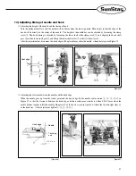
For 470 motor (external synchronizer)
Turn the pulley manually to position the needle bar at the lowest point about to move back up. Then, loosen the fixed
screws on the film as in Figure 10 on page 13 and align the
“
DOWN
”
film with the film adjustment baseline and the
sensor housing baseline as in Figures 14 and 15. Tighten the fixed screws just enough so that the film does not rotate.
In the same way, place the thread take-up lever at the highest point, then loosen the fixed screws again and adjust the
“
UP
”
film as in shown the figure. Be careful that the
“
DOWN
”
film A that was tightened before does not move
when adjusting the
“
UP
”
film.
Figure 15 is an enlarged view of the film location. As in the figure, match the sensor to the end of the arrow.
Sensor
Base
DOWN
Film
Adjusting
Base
Setting the film when
the needle is in a up-
stop position
Setting the film when the
thread take-up lever is at
the highest point
Sensor
Baseline
Setting
Area
Film-Adjusting
Arrow
[Figure 14]
[Figure 15]
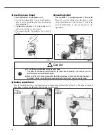
9) Description of back tack button
(for automatic trimming type)
Fix the back tack button or reverse button
①
located beside
the switch box of the table with wooden nail
②
. When the
machine is in a
“
stop
”
mode, you can change the up-down
position of the needle bar by pressing the button. Lightly
pressing the button once when the needle is in a down-stop
position will stop the needle bar in a high position. Pressing
the reverse button twice within less than a second when it is
in an up-stop position will stop the needle bar in a low
position.
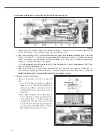
10) Check for machine stop position
(for automatic trimming type)
Check for the machine stop position after moving the needle
up and down by pushing the reverse button
①
. See whether
the line where belt cover A and B meet and the white carved
sign on the bushing are aligned when the needle is in an up
position. If not, adjustment to the photo film of the
synchronizer or to the location of the magnetic holder will
be necessary since there may be problems with the
trimming. In other words, the needle
’
s up-stop position
should be identical with the stop position of the needle bar
after the trimming operation. (See Figure 16)
[Figure 16]
White
carved sign
Needle
up
Needle
Down
Содержание KM-957 Series
Страница 31: ...31 5 Table Drawing 1 KM 967 ...
Страница 32: ...32 2 KM 967 7 ...