30
8-7. Needle and conveying timing
·
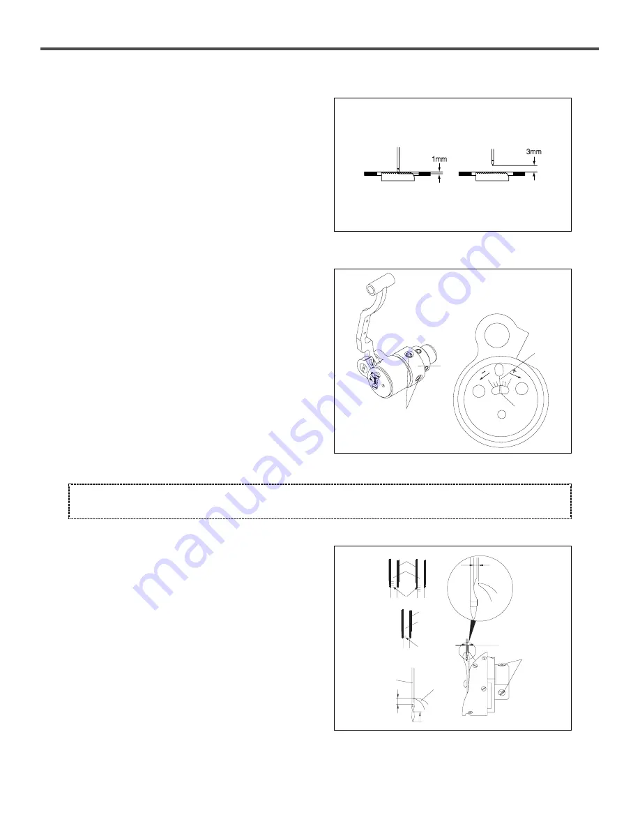
Lower the feed dog
①
from its highest position by turning the
pulley. It is standard that the needle tip is positioned as in the figure,
when feed dog is aligned with surface of the needle plate
②
.
(KM-2300
A and
G)
·
The two surfaces of feed dog
①
and needle plate
②
are aligned
with each other. The needle tip is about 1mm down from the
needle plate
②
. (KM-2300
B and
H)
·
The two surfaces of feed dog
①
and needle plate
②
are aligned
with each other. The distance between the needle tip and the
surface of needle plate
②
is about 3mm.
[ Figure 46 ]
·
Change in lifter cam stop position makes it possible to adjust
conveying timing.
1. Bend the machine body backward.
2. Unfasten a little the two fixing screws
②
of the lifter cam
①
.
3. Adjust the conveying timing by turning left and right the
lifter cam
①
.
4. The standard timing is when lifter shaft carved line
④
is aligned
with the middle line on the bearing cover carved line
③
.
5. Turning the lifter cam
①
in the direction of (+) will make
conveying timing fast. (It is generally used to prevent
puckering.)
6. Turning the lifter cam
①
in the direction of (-) will make
conveying timing slow. (It is generally used to enhance the
thread tightening.)
8-8. Needle and hook timing
1. Raise the needle bar
①
from its lowest position by turning
the machine pulley. As in the figure, align carved line
ⓐ
with the lower part of needle bar down-bushing
②
and
adjust the distance between the upper part of needle hole and
the hook edge at 0 ~ 0.5mm.
2. Loosen three fixing screws
⑤
and align the hook edge
③
with the center of needle
④
. Keep the hook edge
③
0.05 ~
0.1mm away from the needle
④
.
3. Fasten three fixing screws
⑤
completely.
[ Caution ] Too slow conveying timing can cause needle break.
[ Figure 47 ]
[ Figure 48 ]
DB
×
1
DA
×
1
DB
×
1
Heavy Materials
0.05~0.1mm
0~0.5mm
①
②
③
④
②
②
①
①
ⓐ
ⓐ
④
③
⑤
(KM-2300
A, G)
(KM-2300
B, H)
Содержание KM-2300
Страница 2: ......


