ASSEMBLY INSTRUCTIONS
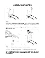
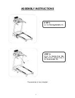
STEP 3:
Insert the
Left Upright Tube Cover
(No. C08)
into the bottom of the
Left Upright
Tube
(No. A05)
. Push down to fasten the
Left Upright Tube Cover
(No. C08)
to the
Base Frame
(No. A01)
.
Repeat the step above to attach the
Right Upright Tube Cover
(No. C09)
to the
Base Frame
(No. A01)
.
STEP 4:
(
*PLEASE SEEK ASSISTANCE FOR THIS STEP!)
Connect the
Top Signal Wire
(No. D04)
to the
Middle Signal Wire
(No. D05)
.
Fix the
Console Base
(No. E)
to the
Left
and
Right Upright Tubes
(No. A05 &
A06)
with 4
Bolts
(No. D50)
and
4
Lock Washers (No. D64)
. Tighten using
Allen
Wrench
(No. B12)
.
8
Содержание SF-T7512
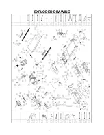
Страница 4: ...EXPLODED DRAWING 3...


