


8
ADJUSTMENTS GUIDE
A
B
15
#80 S14-15-17
48
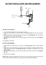
ADJUSTING THE BALANCE
In order to achieve a smooth and comfortable ride, you must
ensure that the stability of the bike is secured. If you notice that
the bike is unbalanced during use, you should adjust the foot
levelers located beneath the Front and Rear Stabilizers of the
bike. To do so, use
Spanner (No. 80)
to loosen 2
Nuts (No. 48)
by turning it
clockwise
(direction A). With the nut loosened, rotate
the
Foot Leveler (No. 15)
until it sits level with the surface that
the bike is on. When you have finished adjusting the foot leveler,
use
Spanner (No. 80)
to re-tighten the 2
Nuts (No. 48)
by turning
it
counter-clockwise
(direction B). If required, repeat this process
to adjust the remaining foot levelers.
8
2
16
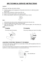
ADJUSTING THE SEAT
The seat of this bike is fully adjustable as it moves
Up
,
Down,
Fore (forward), Aft (backward).
To adjust the height of the
Seat Post (No. 2),
loosen and pull the
Adjustment Knob (No. 16)
outward, then raise or lower the seat
to the desired height. Once adjusted, re-insert and tighten the
Adjustment Knob (No. 16)
to secure the seat in place.
To adjust the seat back and forth, loosen and pull
Adjustment
Knob (No. 16)
outward, then slide the
Seat Slider (No. 8)
to the
desired position. Once positioned, re-insert and tighten the
Adjustment Knob (No. 16)
to secure the seat slider tube in
place.
4
16
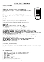
ADJUSTING THE HANDLEBAR
It is important that the handlebar and seat are both set to the
correct height of your body. To adjust the handlebar height,
loosen and pull the
Adjustment Knob (No. 16)
outward, then
slide the
Handlebar Post (No. 4)
up or down to the desired
height. Once adjusted re-insert and tighten the
Adjustment
Knob (No. 16)
to secure the handlebar post in place.
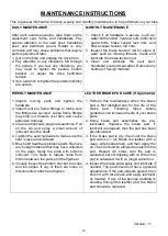
PEDAL STRAP ADJUSTMENT
Your feet should be secured in the toe clips during exercise.
Place your feet as far forward into the toe clips as you can. With
your feet in place, turn the crank to bring one foot to within arm’s
reach, grasp the pedal strap and pull it upward to tighten the toe
clip cage, then insert the strap back into the hoop of the toe clip.
Repeat this process to secure your other foot.
Содержание SF-B1876
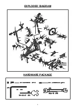
Страница 3: ...2 EXPLODED DIAGRAM HARDWARE PACKAGE...
Страница 15: ...14...


