


29
Table 7-2
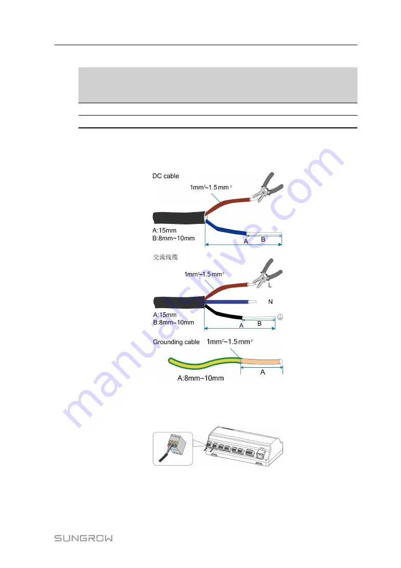
Power cable specification
C
Ca
ab
blle
e
R
Re
ec
co
om
mm
me
en
nd
de
ed
d
c
crro
ossss--sse
ec
cttiio
on
n
L
Le
en
ng
gtth
h o
off c
ca
ab
blle
e
jja
ac
ckke
ett tto
o b
be
e
ssttrriip
pp
pe
ed
d o
offff
L
Le
en
ng
gtth
h o
off
iin
nssu
ulla
attiio
on
n tto
o b
be
e
ssttrriip
pp
pe
ed
d o
offff
DC cable, AC cable
1mm
2
~1.5mm
2
15mm
8mm~10mm
Grounding cable
1mm
2
~1.5mm
2
8mm~10mm
-
Power cable wiring steps are as follows:
Step 1
Strip the cable jackets and insulation layers of the DC cable, AC cable, and grounding
cable with a wire stripper by appropriate length.
Step 2
Insert the stripped DC cable into the "24V IN" and "24V OUT" ports of the Logger1000.
Connect the DC cable led from the "24V OUT" port of the Logger1000 to other devices
that need 24V DC power supply.
Step 3
Connect the stripped grounding cable to the corresponding port of the Logger1000.
User Manual


