75
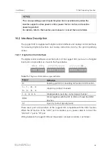
10.3.2.5 Digital Input
When using the digital signal at the DI port of the Logger1000 as the dispatching input,
set the reactive control mode to "Digital input".
Step 1
Click "Power control" -> "Reactive power" to enter the reactive power interface.
Step 2
Set the reactive control mode to "Digital input".
Step 3
Set DI control parameters. For specific parameter description, refer to the following
table.
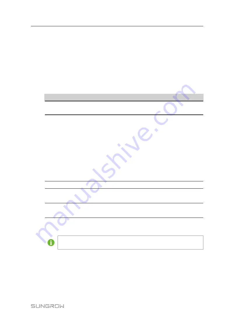
Table 10-10
Parameter description
P
Pa
arra
am
me
ette
err
D
De
essc
crriip
pttiio
on
n
Communication
abnormality output (%)
Communication is abnormal, and specified dispatch
output value is delivered.
Control method
Open loop control: Reactive instruction controlled by DI is
sent to power output port of the inverter, thereby
achieving active power control.
Closed-loop control: Reactive instruction controlled by DI
is used as target value and reactive power and power
factor of the meter need to be collected and used as
input parameters, and reactive power compensation ratio
is calculated and sent to power output port of the inverter.
Generally, this strategy is used for improving the power
factor of the property boundary point.
Select energy meter*
Select Smart Energy Meter involved in power regulation
Control cycle
Time interval of delivering dispatching instructions
Parameter range: 5~60s
Q-Method
PF: set the power factor as the target value
%: set reactive power percentage
Note: *Only when the control method is set to "Closed-loop control", the parameter "-
Select energy meter" is settable.
The open-loop control has the "PF" Q-Method, and the closed-loop control
has the "PF" Q-Method only when the meter is selected.
Step 4
Add digital input manner
Select the desired DI channel, fill in the "Percentage "(PF), and click "Save".
-- -- E
En
nd
d
S
Su
ub
bsse
eq
qu
ue
en
ntt O
Op
pe
erra
attiio
on
n
Delete digital input manner: select a digital input manner that needs to be deleted, and
click "Clear data".
User Manual


