background image

2

Sunflare Components List 

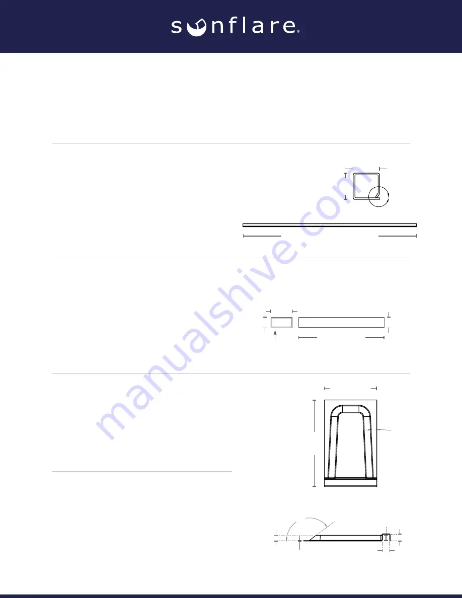
•  Metal Standing Seam Roof Width Requirement

In order for the PowerFit20 to be properly installed, the width between the internal 

peaks of the seams must be no less than 15.5”.  The PowerFit20 is only compatible 

with flat standing seam roofs. Any striations or other non-flat surfaces may prevent the 

module from adhering for the intended lifetime.

•  WMS Spacer Tube

Specs: 203.2 x 50.8 x 25.4 mm 

Description: PVC spacer tube used for 

two functions: 1) as placement between 

two adjacent modules and 2) as a way 

to adhere the junction box to the roof. 

The spacer tube comes with two sides of 

adhesive to install onto the roof and the 

bottom of the junction box cover.

•  WMS Wire Conduit

Specs: 1675.0 x 31.75 x 31.75 mm 

Description: PVC wire conduit that runs 

parallel with the peak of each seam. It 

will be justified to one side of the seam 

and allow for a clean wiring for each 

module to go to the roof cap. This piece 

will be installed with the butyl-based 

adhesive included with the component.

•  WMS Junction Box Cover

Specs: 388.3 x 235.0 x 31.9 mm 

Description: PVC junction box cover used 

to house and protect the wiring between 

two adjacent modules. It will be adhered 

using DOW 804 adhesive to create a 

water-tight seal.

31.75±2 mm 

[1.25±0.1 in]

Profile View

Top-Down View

31.75±2 mm 

[1.25±0.1 in]

1675.0±2 mm [65.9±0.1 in]

Profile View

Top-Down View

50.8±2 mm 

[2.0±0.1 in]

R1.0

25.4±2 mm 

[1.0±0.1 in]

25.4±2 mm 

[1.0±0.1 in]

203.2±2 mm 

[8.0±0.1 in]

Profile View

Top-Down View

235.0±2 mm 

[9.25±0.1 in]

388.3±2 mm 

[15.28±0.1 in]

25.86±2 mm 

[10.2±0.1 in]

2.0±2 mm 

[0.08±0.1 in]

32.15±2 mm 

[1.27±0.1 in]

29.86±2 mm 

[1.18±0.1 in]

31.86±2 mm 

[1.25±0.1 in]

2.63°

142°

•  8” Jumper Cable

Specs: 8” long. 10AWG PV wire with 

MC4 heads 

Description: Pre-cut MC4 PV cabling for 

an easy connection between two adjacent 

modules. This cable will be housed 

underneath the junction box cover.

Содержание PowerFit20

Страница 1: ...Installation Instructions for the PowerFit20 Photovoltaic Modules...

Страница 2: ...ed to one side of the seam and allow for a clean wiring for each module to go to the roof cap This piece will be installed with the butyl based adhesive included with the component WMS Junction Box Co...

Страница 3: ...re conduit This will allow for a more structurally sound install along with creating a water proof sealant to prevent debris from entering the WMS Other Required Components Inverters Consult your inst...

Страница 4: ...e shall not be considered to comply with the requirements of UL1703 unless the module is mounted with hardware that has been tested and evaluated with the module under this standard or by field inspec...

Страница 5: ...nd death Do not attempt to install service remove touch or modify a damaged module Damaged modules should only be removed by qualified professionals wearing appropriate personal protection equipment f...

Страница 6: ...nt electricity from being generated Do not wear metallic jewelry including ear nose and lip rings watchbands pins or any other metallic object during installation or troubleshooting of photovoltaic sy...

Страница 7: ...Management System WMS is certified as Class A over any Class A metal standing seam roofing constructions Metal Roof Manufacturer Approvals The PowerFit20 module is fully engineered to reduce stresses...

Страница 8: ...e flat space Use a rubber wheeled roller to ensure the proper pressure is applied to the module Module Installation After the roof has been cleaned to the requirements above the components can be adhe...

Страница 9: ...s that are opposite the side of the WMS wire conduit pieces Using the 7 5 MC4 jumper cables connect one end to the module located on the upward slope and run it through the WMS wire conduit towards th...

Страница 10: ...de of the junction box cover should go over and around the WMS wire conduit to ensure a watertight seal Apply pressure to the junction box cover to complete the installation Repeat this process until...

Страница 11: ...ions with the PowerFit20 modules No more than 6 modules should be connected in series to one AP Smart component Doing any more will result in failure of the PV system Figure 11 Shows the proper connec...

Страница 12: ...eplace any WMS junction box cover that is damaged or significantly degraded If a module is damaged leave it in place Do not attempt to remove the module from the roofing surface unless it poses an ele...

Страница 13: ...o any roofing products with which they may come in contact Sunflare accepts no liability for damages financial losses of any kind business interruptions or lost earnings whether they be direct or inci...

Отзывы: