Chapter 2
Hardware Installation
2-21
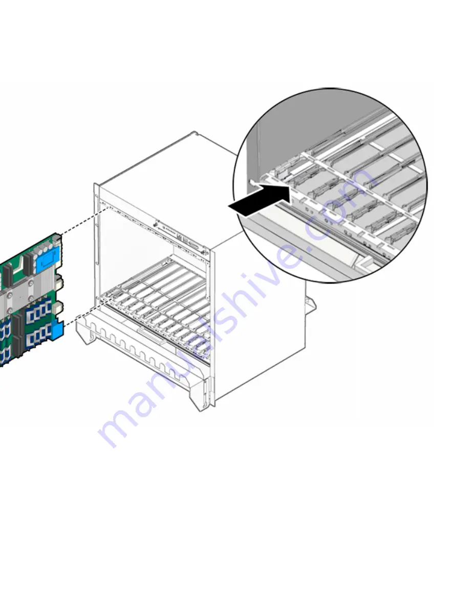
FIGURE 2-7
Installing Blade Server Into Chassis Slot
6. Push the blade server slightly into the midplane connectors, and then close the
latches to seat the blade server in the connectors (
FIGURE 2-8
).
7. When the lower latch is closed, the blue Hot-Swap LED blinks while the blade
server is initializing. The blue LED turns off and the green OK LED lights when
the blade server is ready.
8. Tighten the locking screws to ensure the blade server is secured into the shelf
(
FIGURE 2-8
).
Содержание Sun Netra CP3260
Страница 18: ...xviii Sun Netra CP3260 Blade Server User s Guide April 2009...
Страница 22: ...1 4 Netra CP3260 Blade Server User s Guide April 2009 FIGURE 1 1 Netra CP3260 Blade Server Front Panel...
Страница 23: ...Chapter 1 Introduction 1 5 FIGURE 1 2 Netra CP3260 Blade Server Top View...
Страница 24: ...1 6 Netra CP3260 Blade Server User s Guide April 2009...
Страница 27: ...Chapter 1 Introduction 1 9 FIGURE 1 3 Netra CP3260 Blade Server in an ATCA Shelf Enclosure...
Страница 36: ...1 18 Netra CP3260 Blade Server User s Guide April 2009...
Страница 42: ...2 6 Netra CP3260 Blade Server User s Guide April 2009 FIGURE 2 1 FB DIMM Memory Locations...
Страница 43: ...Chapter 2 Hardware Installation 2 7...
Страница 44: ...2 8 Netra CP3260 Blade Server User s Guide April 2009...
Страница 52: ...2 16 Netra CP3260 Blade Server User s Guide April 2009 FIGURE 2 5 TOD Battery Location...
Страница 53: ...Chapter 2 Hardware Installation 2 17...
Страница 61: ...Chapter 2 Hardware Installation 2 25 FIGURE 2 9 Hot Swap Latch and Hot Swap LED...
Страница 62: ...2 26 Netra CP3260 Blade Server User s Guide April 2009...
Страница 105: ...Chapter 5 Hardware Functional Descriptions 5 5 FIGURE 5 2 UltraSPARC T2 Multicore Processor Block Diagram...
Страница 106: ...5 6 Netra CP3260 Blade Server User s Guide April 2009...
Страница 140: ...B 8 Netra CP3260 Blade Server User s Guide April 2009...


