Summa SUMMACUT Скачать руководство пользователя страница 79


Maintenance  

5-1 


5


Maintenance and Cleaning 


5.1 

Introduction 

 
The SummaCut cutter range has a number of sliding surfaces made of smooth metals and 
plastics. They are virtually friction-free and require no lubrication. They will, however, collect 
dust and lint that may affect the cutter’s performance. Keep the cutter as clean as possible 
by using a dust cover. When necessary, clean the unit with a soft cloth dampened with 
isopropyl alcohol or mild detergent. Do not use abrasives. 
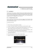
 

5.1.1 

Cleaning the drive system 

 
Over time, the sleeves of the drive drum may become clogged with accumulated residue 
from the media liner. This may cause the media to slip between the pinch rollers and the 
drive sleeves, decreasing traction. 
 

Cleaning the drive system: 


1.


Make sure there is no media loaded in the cutter. 

2.


Switch cutter off and disconnect the cutter from the mains. Raise the pinch rollers. 

3.


Put a pinch roller above the sleeve that needs to be cleaned. Make sure it is the outer 
left or the outer right pinch roller (otherwise there is not enough pressure). 
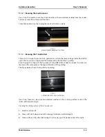
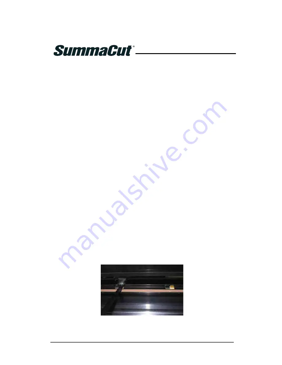
4.


Remove the backing from a piece of vinyl. Place the piece of vinyl between a pinch 
roller and drive sleeve with the tacky side down. Lower pinch roller. 

5.


Turn on another yellow drive sleeve by hand so that the piece of vinyl is winding on the 
sleeve for at least one turn. 

6.


Then pull the piece of vinyl from underneath the pinch roller. 

7.


Repeat several times until all residue is removed from the drive sleeves.  
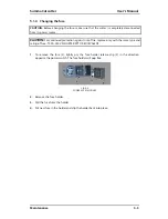


FIG 5-1 

5-1 

PLACEMENT OF VINYL STRIP 


Содержание SUMMACUT

Страница 1: ...User s Manual Rev 004...

Страница 2: ...for radio noise for digital apparatus set out in the Radio Interference Regulations of the Canadian Department of Communications Notice Summa reserves the right to modify the information contained in...

Страница 3: ...mma Inc 10001 Lake City Way NE Seattle WA 98125 USA Main Office 1 206 527 1050 1 800 527 7778 Fax 1 206 527 1046 Support support summa us Sales sales summa us Web Site www summausa com Summa East Inc...

Страница 4: ...t is Summa s most popular and affordable line of vinyl cutters They offer tracking accuracy speed and features not found in other affordably priced cutters SummaCut now offers the unrivaled Optical PO...

Страница 5: ...g the Cutter to the Mains 1 9 1 3 1 Grounding Earthing 1 9 1 3 2 Operating voltage 1 9 1 3 3 Powering on the cutter 1 10 1 4 Connecting the Cutter to a Computer 1 11 1 4 1 USB connection 1 11 1 4 1 1...

Страница 6: ...to Make Sure the Sign Has the Correct Size 2 9 3 OPOS Optical POSitioning 3 1 3 1 Introduction 3 1 3 2 Basic OPOS operation 3 1 3 2 1 OPOS calibration 3 2 3 2 2 Media calibration 3 3 3 3 Detailed OPOS...

Страница 7: ...est 4 5 4 3 3 Tool 4 5 4 3 4 FlexCut Mode 4 5 4 3 5 Panels 4 6 Sort Vectors 4 6 4 3 6 Velocity 4 6 4 3 7 Overcut 4 7 4 3 8 OptiCut 4 7 4 3 9 Emulation Lang 4 7 4 3 10 USB Class 4 8 4 3 11 Baud Rate 4...

Страница 8: ...nformation 6 1 6 1 Models 6 1 6 2 Features List 6 1 6 2 1 Hardware 6 1 6 2 2 Interface 6 1 6 2 3 Functionality 6 1 6 2 4 Software 6 2 6 2 5 CUTTER ACCESSORIES AND CONSUMABLES 6 3 6 3 Technical Specifi...

Страница 9: ...osition media flange on cutter 1 15 1 19 Feeding roll media without using media flanges 1 16 1 20 Media position 1 16 1 21 Pinch roller lever 1 17 1 22 Removing the drag knife holder from the clamp 1...

Страница 10: ...screws CAUTION For safety reasons no fewer than two people should be involved in unpacking the cutter 1 1 1 Removing the packaging from the cutter 1 Remove the straps and the staples and open the lid...

Страница 11: ...r accessories to mount the stand FIG 1 2 1 2 CONTENTS OF BOX STAND 2 The box containing the basket should contain following a Total of 7 tubes for media basket b Linen media basket c Bag of accessorie...

Страница 12: ...rn the stand upside down and mount the 4 casters put the nut first in the casters then use the 12mm wrench FIG 1 6 1 6 MOUNTING THE 4 CASTERS 6 Turn the stand the right way up again and put the machin...

Страница 13: ...e without a stand The smaller models are equipped with an extra media guide In order not to damage this part special attention is requested when putting a machine on a surface This media guide should...

Страница 14: ...to ensure that wide media stays flat in the middle The extra rollers in the middle can be enabled or disabled 2 Keypad All cutter activity can be initiated from keypad The LCD displays information abo...

Страница 15: ...nce cutting is done on the cutting strip it is essential that the strip remains intact 7 Media sensor A media sensor behind the right sleeve is used to detect the end of the loaded media 8 Media guide...

Страница 16: ...rollers to ensure that wide media stays flat in the middle The extra rollers in the middle can be enabled or disabled 2 Pinch roller lever This lever is used to raise and lower the pinch rollers for...

Страница 17: ...i directional communication between the host computer and the cutter 7 RS 232 port This DB 9P connector provides serial bi directional communication between the cutter and a host computer 8 Screws to...

Страница 18: ...ormer motor generator set The wall sockets into which the cutter is plugged must be of the grounded type The grounded conductors serving the wall socket must be properly connected to the ground For em...

Страница 19: ...AC power cord into the receptacle located in the power entry module on the cutter s rear panel 2 Plug male end of the AC power cord into a properly grounded wall socket 3 Power on the cutter by pressi...

Страница 20: ...n the cutter see section 1 3 3 and return to the computer The Found New Hardware Wizard should appear on the computer screen and install the USB driver 8 Click OK and follow the instructions provided...

Страница 21: ...s CD ROM drive 6 Click on the USB install driver icon on the CD ROM This will automatically install the driver and the Summa Port Mapper utility 7 Remove the CD from the CD ROM drive 8 Restart the com...

Страница 22: ...ters of the RS 232 connection must be set in either the properties of the COM port in the device manager or in the cutting software program itself Please refer to the manual for the cutting software o...

Страница 23: ...fully raised before sliding them to the left or right Always hold the assembly at the side of the pinch roller to move it from left to right do not reposition pinch roller by holding the assembly at...

Страница 24: ...The following illustration shows a loosened flange 1 and a tightened flange 2 FIG 1 17 1 17 MEDIA FLANGES 3 Insert a loosened flange into one end of the media roll and tighten the knob Verify that the...

Страница 25: ...uld be positioned over the drive sleeves about 3 to 15 mm 0 1 to 0 6 away from the media s outer edges 1 Then pull on the media while holding the flange at the back so the media is tight FIG 1 20 1 20...

Страница 26: ...ARE HAZARDOUS MOVING PARTS 8 Lower the pinch roller lever to press the media firmly against the drive sleeves After one second the tool carriage automatically moves from the right to the left to sens...

Страница 27: ...while the cutter is not being used The minimal loading procedure consists of A media width measurement Media is unwound over a length equal to the width measured between the outer two pinch rollers A...

Страница 28: ...receive data from the computer 4 Or press to cancel The cutter will move to its original origin and come online Extended load The function extended load makes it possible to define the limits of the Y...

Страница 29: ...Simply turn out the knife see fig 1 22 yellow arrow clockwise to start cutting Below is the complete description of the knife removal and knife installation Removing the drag knife 1 Loosen the head c...

Страница 30: ...ow end of the holder gently push the knife all the way in 3 Turn the holder upside down and tap it lightly on a solid surface to ensure that the knife is completely inserted 4 Slowly turn the knurled...

Страница 31: ...ed Once is pressed the current knife pressure value will be set automatically to the new value and the cutter will cut the knife pressure test pattern FIG 1 26 1 26 KNIFE PRESSURE TEST PATTERN Peel ou...

Страница 32: ...Do not operate the cutter if the knife blade cuts through the media backing as this will seriously damage the cutter s rubber cutting strip and the knife CAUTION For most vinyl cutting operations the...

Страница 33: ...m the clamp 2 Install the pen in the clamp and tighten the clamp screw 3 The change of tool can either be input on the control panel or with Summa Cutter Control PC only or with the cutting software S...

Страница 34: ...he cutter The various menu and submenu items are always presented in a loop which means that when the last menu or submenu item is displayed pressing the appropriate key will automatically take you ba...

Страница 35: ...is key is not pressed a changed value of a menu item is not saved internally and can will be lost if the menu is left 2 1 1 4 The test key If there is a certain test routine in a submenu then it can b...

Страница 36: ...ncing tool is installed Do not replace the standard knife pen or pouncing tool with products from other manufacturers Each keystroke can initiate an internal test or movement of head or media WARNING...

Страница 37: ...ag knife offset A very important parameter for a drag knife is the offset The offset is the distance between the knife center and the knife tip NOTE Knife offset should be set each time the knife is c...

Страница 38: ...nife offset test 2 Press to confirm the chosen knife offset 3 Press to leave the offset unchanged When the knife offset is set correctly the test pattern looks like this FIG 2 2 2 2 CORRECT KNIFE OFFS...

Страница 39: ...raised or lowered accordingly There is one fixed speed the speed at which the cutter pulls the media from the roll This speed is fixed at 200mm s 8ips Setting the cutting speed 1 Power on the cutter 2...

Страница 40: ...osen parameter The value will change on the LCD 8 Press to confirm An asterisk will appear before the value indicating it is now the selected setting 9 Press twice to leave the menu NOTE Velocity is t...

Страница 41: ...E Factory default values for the different users are all set the same Changing the User Configuration 1 Power on the cutter 2 Press Velocity will appear on the LCD 3 Use or to scroll through the menu...

Страница 42: ...2 However if high accuracy between different vinyl or colors is needed then calibration is necessary Calibrating the media Length calibration 1 Power on the cutter load media and mount knife see secti...

Страница 43: ...he cutter to Metric to do the calibration It is more accurate than the English unit system see Error Reference source not found 7 Use and to change the value on the LCD to the measured length of the d...

Страница 44: ...contact your software dealer for specifics In general contour cutting includes the following steps Create a graphic Print the graphic laminate if necessary Load the graphic into the cutter Set the nec...

Страница 45: ...4 Press System Setup will appear on the LCD 5 Press Confidence will appear on the LCD 6 Use or to scroll through the menu until Cal OPOS is reached press The cutter will cut out a square measuring ap...

Страница 46: ...r OPOS If the media calibration is done and results are not better then set the media calibration value again to default 30 see further in the procedure how Doing media calibration 1 Turn on the cutte...

Страница 47: ...y in the middle and slightly to the bottom right 10 Press to confirm The cutter will make a circular movement while it measures the reflection of the marker color It will briefly display the measured...

Страница 48: ...ues Place contour lines just inside the graphics recommended 1 Place contour lines outside the graphics 2 Create thick borders around graphics and place contour lines inside these borders 3 1 contour...

Страница 49: ...istance 1 is the distance from the lower left corner of one marker to the lower left corner of the next marker and depends on several factors The X Distance must be known when setting the OPOS paramet...

Страница 50: ...ate layer Copy the origin marker for origin reference in the layer of the contours NOTE The layer with the graphic and the layer with the markers must be printed out The layer with the contour lines a...

Страница 51: ...e rest of the design When OPOS XY is enabled then the OPOS sensor will measure points along the extra line The number of measuring points will be calculated by the cutter and will depend on the width...

Страница 52: ...l make sure that the graphic s Origin marker coincides with the media s origin 1 1 2 Make sure there is at least a 1cm 0 4in margin on each side of the graphic 2 A 2cm 0 8in margin is preferable There...

Страница 53: ...edure Range X distance 30 mm to 1300 mm Y distance 30 mm to 1600 mm X size 1 2 mm to 10 mm Y size 1 2 mm to 10 mm Marker Count on one line 2 to 54 Changing OPOS setting manually 1 Power on the cutter...

Страница 54: ...Press or to change the value of the chosen parameter The value will change on the LCD 9 Press to confirm An asterisk will appear before the value indicating it is now the selected setting 10 Press tw...

Страница 55: ...gh the menu until Align Load is reached then press A message prompting the user to set the knife above the first marker will scroll across the LCD 4 Use and to do so and press The cutter will reload t...

Страница 56: ...o that the Origin marker 1 is situated in the bottom left corner of the cutting area 2 as viewed on the screen If your cutting software s default orientation is not set to landscape the contours and m...

Страница 57: ...en the automating features may be used If the cutter s RAM is less than the job s file size then the automating features may not be used 3 4 1 Cutting multiple copies of a graphic on the same roll If...

Страница 58: ...value of the chosen parameter will appear on the LCD 8 Press or to change the value to ON ON will appear on the LCD 9 Press to confirm An asterisk will appear before ON indicating it is now the selec...

Страница 59: ...tation of the first sheet When in OPOS sheet mode the cutter stores the distance between edges of the sheet and the first OPOS marker TIP Use easy orientation points to be able to quickly position the...

Страница 60: ...started from the computer The cutting software will usually have a button or a command called scan a bar code First make sure that the media is loaded FIG 3 2 3 2 OPOS BARCODE JOB LOADED Start the pro...

Страница 61: ...ed in section 3 3 6 The cutter will read the barcode and send this data to the computer The cutting software will then automatically send the correct cutting data to the cutter The cutter will start s...

Страница 62: ...line The software sends then first the data of the contour lines to the cutter and then it activates FlexCut panelling mode and vector sorting and sends the data for cutting through to the cutter If t...

Страница 63: ...f the parameters to check the result The cutter will cut out a pattern to check if the settings are usable 10 Check if the result is the satisfactory If not change one of the parameters above Reducing...

Страница 64: ...ter that needs to be changed The menu can scroll through from on or off panels size recut and sorting 15 Press or to change the value of the chosen parameter The value will change on the LCD 16 Press...

Страница 65: ...monly used touch screen manipulation This section may be used as a reference for locating a certain parameter setting or test The less frequently used parameters are also explained in this section The...

Страница 66: ...l name This parameter is explained in section 2 2 2 4 2 4 Knife offset This parameter is explained in section 2 2 3 4 2 5 Pouncing Gap The pouncing gap submenu is used to set or modify the distance be...

Страница 67: ...is menu can be used when loading sheet material During the loading the maximum material length can be set 4 2 10 Extended Load This parameter is explained in section 1 5 3 4 2 11 Align Load Align load...

Страница 68: ...SummaCut cutter User s Manual Detailed Operation 4 4 4 3 System Setup Menu only available when the tool is set to drag knife FIG 4 2 4 2 CONFIGURATION MENU...

Страница 69: ...ill alternately cut a certain length with full pressure and a certain length with reduced pressure The advantage of the FlexCut feature is that it cuts completely through the material yet allows the m...

Страница 70: ...eplot OFF vector sorting DIREC Tracking difficult media Typical settings for the parameters are then Panels ON Panel size 3 10cm Panel replot ON OFF depending on the thickness of the media vector sort...

Страница 71: ...004 FIG 4 3 4 3 OVERCUT Press then use or to change the value Press to confirm or to cancel The default overcut is set to 1 4 3 8 OptiCut OptiCut increases the cutting quality in case the knife is wor...

Страница 72: ...The change in USB class becomes active only after rebooting the cutter NOTE The USB id in the cutting software has to be the same as the chosen USB id in the cutter Each time a new USB is select on t...

Страница 73: ...ter receives Press then use or to change Press to confirm or to cancel The parity is default set at None 4 3 13 RTS DTR RS232 This parameter controls the handshake between cutter and computer Possible...

Страница 74: ...ment These alignment methods can be used if the combination of marker color media color cannot be read by the OPOS sensor These alignment methods require that the user manually register markers using...

Страница 75: ...This submenu is used to set or modify the dialogue language on the touch screen When the machine is new it asks the user to choose a language If this setting was set to the wrong language it can be c...

Страница 76: ...ing whether the media sensor is functioning properly and whether the switching levels of the sensor is correctly set 1 Press 2 Put a piece of media half on the sensor and under the two outer pinch rol...

Страница 77: ...and 400g pressure To execute this test a tension gauge of 100 gr and 600 gr is required Measure the pressure on the knife with the tension gauge read value from the gauge when knife just lifts from th...

Страница 78: ...eter is not explained OPOS paneling OPOS Paneling With this option the markers can be read in panels The OPOS sensor will read markers according to panel size instead off loading them all be OPOS Pane...

Страница 79: ...between the pinch rollers and the drive sleeves decreasing traction Cleaning the drive system 1 Make sure there is no media loaded in the cutter 2 Switch cutter off and disconnect the cutter from the...

Страница 80: ...are on top and on the bottom of the front of the Y guiding Even though the shape of the Y guide rail may differ from model to model the areas are located in the same place at the top and bottom of th...

Страница 81: ...tion against risk of fire replace only with the same type and rating of fuse T2 0A 250V SCHURTER SPT OR EQUIVALENT 1 To remove the fuse 3 lightly pry the fuse holder release clip 2 in the direction op...

Страница 82: ...x Stand with basket Optional on D60 and D75 x Back Media sensor x OPOS Configuration depended x With barcode recognition x OPOS 2 0 sensor on D60FXSE x OPOS X sensor automatically raised and lowered...

Страница 83: ...CS CS5 x Nesting paneling weeding box and cut by color possibilities x Integration of OPOS x MacSign Cut x Bridge program to cut artwork created in other programs x Mac OS 9 Mac OSX 10 2 or higher x...

Страница 84: ...423 183 USB Cable 399 111 1x Standard knife set of 5x 391 360 2 knives Standard knife holder 391 332 1x Sandblast knife set of 5x 391 358 Sandblast knife holder 391 363 Fibre tip pen black set of 4 MP...

Страница 85: ...8 350 13 8 680 26 8 680 26 8 680 26 8 Weight 15 kg 33 lbs 17 kg 37 lbs 42 kg 92 lbs 48 kg 106 lbs 54 kg 119 lbs TABLE 2 MACHINE DIMENSIONS 6 3 2 Shipping dimensions D60 D75 D120 D140 D160 mm inch mm i...

Страница 86: ...wide Thickness 0 05 to 0 25 0 8mm with optional sandblast knife 0 002 to 0 01 0 03 inch with optional sandblast knife 1 Larger Media lengths can be handled but compliance with specifications is not g...

Страница 87: ...0 to 400 gr Pen pressure 0 to 400 gr Pouncing pressure 0 to 250 gr Valid within the guaranteed tracking length see table 3 Not valid in Oversized Mode Excludes differences due to media expansion stre...

Страница 88: ...ional stability of media let it stabilize to the current environmental conditions before usage for a minimum period of 24 hours 6 3 8 Electrical The power entry module detects the line voltage and swi...

Страница 89: ...accessories Part description Part number Picture Manual and driver CD MD9045 Power cable Regional differences contact local dealer for exact part number USB cable 399 111 Serial cable 423 183 Media f...

Страница 90: ...Plotter pen set of 4 MP06BK Drag knife holder for sandblast knife 391 363 Drag pouncing pin holder 391 595 Pouncing pin 391 592 Fuse MF9003 Cutting strip short 391 386 Cutting strip long 400 565 Pounc...

Отзывы: