


SummaCut cutter
User’s Manual
Setup
1-8
4.
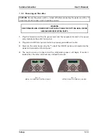
Power On/Off switch:
This rocker switch, in the middle of the power entry module, sets
the cutter’s power to ON or OFF. To switch on the power, press the “I” side of the rocker
switch. To switch off the power, press the “O” side of the rocker switch.
5.
AC power cord receptacle
: It is located at the left-hand side of the power entry
module. The power-up procedure is explained in detail in Section 1.3. Always use a
power cord that was delivered with your cutter.
6.
USB port:
This interface is based on the standards specified in Universal Serial Bus
Specifications Revision 1.1. It allows a high-speed bi-directional communication
between the host computer and the cutter.
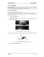
7.
RS-232 port:
This DB-9P connector provides serial bi-directional communication
between the cutter and a host computer.
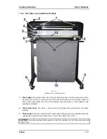
8.
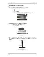
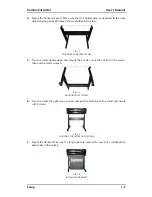
Screws to secure the cutter base:
Screws (2 left and 2 right) hold the cutter base to its
stand. All the screws must be properly tightened before using the cutter.
9.
Casters:
The casters on the stand are equipped with locking brakes. Once the cutter has
been moved to its new location, press the brakes with your foot to lock the casters.
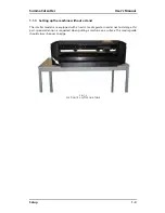
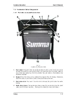
10.
Media basket:
The stand and linen media basket come as standard equipment with all
120, 140 and 160 SummaCut cutters.
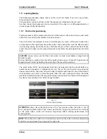
11.
Roll media guide bushes:
The two flange guides serve to keep the media roll in place
when media is pulled from the roll.
12.
Media support rollers:
Rotating support rollers for the media roll.
Содержание SUMMACUT
Страница 1: ...User s Manual Rev 004...


