13
7.4
Motor housing
It is advisable to mount the oil plugs back on the oil cas-
ing to avoid unnecessary spill of oil.
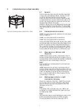
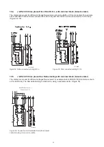
J 205:
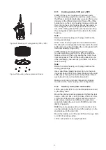
Mount a lifting chain/wire with two screws on the
upper part of the motor housing and keep it in an up-
right position secured by the lifting crane. Unscrew the
nuts holding the motor housing/oil casing together and
lift off the motor housing. (Disconnect the cable for the
leakage sensor). (Figure 16)
J 405:
MOUNT THE HANDLE BACK TO THE MOTOR
HOUSING. Use a lifting crane to lift the pump in the
handle to an upright position standing on the stud bolts.
Unscrew the nuts holding the motor housing (use a pipe
tong to contra hold the diffuser stud bolts) and lift off
the motor housing separating it from the rotor/oil casing
package (Disconnect the cable for the leakage sensor ).
(Figure 16)
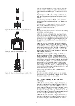
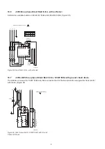
J 604:
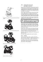
Keep the pump secured by the lifting eye bolt on
the shaft end and the lifting crane. Disconnect the cable
for the leakage sensor and bearing sensor. Unscrew the
nuts and lift off the oil housing together with the rotor +
shaft from the motor housing. Release the seal leakage
monitor plug out of its rubber housing and the lower
bearing monitor plug out of the bearing flange. (Figure
17)
7.5
Rotor + shaft and ball bearings
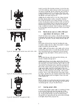
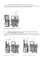
J 205
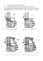
: Keep the rotor unit standing upright and un
-
screw the lower bearing bracket. Lift out the rotor with
bearings from the oil casing (Can be lifted manually or
alternatively a lifting strap can be attached to the upper
bearing). Use a bearing puller to remove both bearings
from the shaft (Use a long arm puller for the lower bear-
ing). (Figure 18)
J 405:
Lift the rotor unit standing upright and unscrew
the lower bearing bracket. Remove the upper bearing
with a puller and mount a lifting bow on the shaft end
and lift out the rotor from the oil casing. (Alternatively a
lifting strap can be attached to the upper bearing to lift
out the rotor from the oil casing). Use a bearing puller
with long arms to remove lower bearings from the shaft.
(Figure 18)
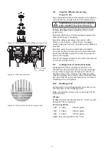
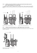
J 604:
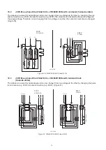
Dismantle the oil housing from the rotor + shaft
completely. Unscrew the screws on the bearing flange.
Place the oil housing on the auxiliary tool on the press.
Press out the rotor + shaft with the lower bearing of the
oil housing. The bearing seat can be heated quickly
with LP-gas to facilitate the removal. (Figure 19)
Hint!
Make sure the oil casing is well supported on the
press when the rotor with bearings is pressed out. This
is to avoid unwanted changes on the bearing seat on
the oil casing.
Hint!
Place a hard rubber sheet under the table in order
to avoid damage to rotor shaft and upper bearing.
Remove the circlip under the lower ball bearing. Lay
the rotor + shaft down on the side. Use a bearing puller
with long arms to remove lower bearings from the shaft.
Figure 16: Removal of motor housing (J 205, J 405)
Figure 17: Removal of motor housing (J 604)
Figure 18: Removal of rotor unit (J 205, J 405)
Figure 19: Removal of rotor unit (J 604)
Содержание J 205
Страница 1: ...en www sulzer com Submersible Drainage Pump J 205 J 405 J 604 Workshop Manual 00831887 02 2020 ...
Страница 30: ...30 11 Sectional drawing Tools J 205 ...
Страница 31: ...31 J 405 ...
Страница 32: ...32 J 604 ...
Страница 37: ...37 ...


