


SECTION 4
ES-8 MOBILE APPLICATION MANUAL R00
17
4.6
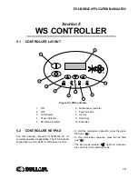
CONTROL SYSTEM,
FUNCTIONAL DESCRIPTION
The purpose of the compressor control system is to
regulate the amount of air being compressed to
match the amount of compressed air being used.
The capacity control system consists of a solenoid
valve, regulator valve and an inlet valve. The
functional description of the control system is
described below in 4 distinct phases of operation.
The following description text applies to all Series
ES-8 compressors. For explanitory purposes, this
description will apply to a compressor with an
operating range of 100 to 110 psig (6.9 to 7.6 bar). A
compressor with any other pressure range would
operate in the same manner except stated
pressures.
START MODE—0 TO 60 PSIG (0 TO 4.2
BAR
)
When the compressor “I” pad is depressed, the sump
pressure will quickly rise from 0 to 60 psig (0 - 4.2
bar). During this period, both the pressure regulator
and the solenoid valve are closed, the inlet valve is
fully open and the compressor pumps at full rated
capacity. The rising compressor air pressure is
isolated from the service line in this phase by the
minimum pressure valve set at approximately 60 psig
(4.2 bar).
FULL LOAD MODE—60 TO 100 PSIG (4.2
TO 6.9
BAR
)
When the compressed air pressure rises above 60
psig (4.2 bar), the minimum pressure valve opens
allowing compressed air to flow into the service line.
From this point on, the line air pressure is continually
monitored by the Supervisor. The pressure regulator
and the solenoid valve remain closed during this
phase. The inlet valve is in the fully open position as
long as the compressor is running at 100 psig (6.9
bar) or below.
MODULATING MODE—100 TO 110 PSIG
(6.9 TO 7.6
BAR
)
If less than the rated capacity of compressed air is
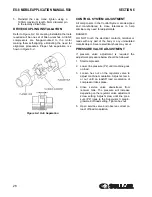
being used, the service line pressure will rise above
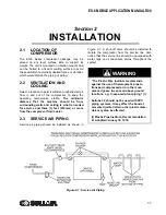
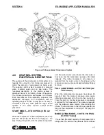
Figure 4-2: Encapsulated Compressor System
Содержание 30XH
Страница 10: ...NOTES 10 ...
Страница 22: ...NOTES 22 ...
Страница 33: ...NOTES 33 ...
Страница 34: ...INLET CONTROL SEAL DRIVE GEAR AND PARTS 34 8 3 INLET CONTROL SEAL DRIVE GEAR AND PARTS ...
Страница 36: ...MOTOR COUPLING FAN AND PARTS 36 8 4 MOTOR COUPLING FAN AND PARTS ...
Страница 40: ...COMPRESSOR COOLER SYSTEM AND PARTS 40 8 6 COMPRESSOR COOLER SYSTEM AND PARTS ...
Страница 42: ...PNEUMATIC CONTROL SYSTEM AND PARTS 42 8 7 PNEUMATIC CONTROL SYSTEM AND PARTS ...
Страница 44: ...CONTROL STARTER MFV 44 8 8 CONTROL STARTER MFV ...
Страница 46: ...DECAL GROUP 46 8 9 DECAL GROUP ...
Страница 48: ...DECAL GROUP 48 8 9 DECAL GROUP CONTINUED ...
Страница 50: ...WIRING DIAGRAM FULL VOLTAGE STANDARD 50 8 10 WIRING DIAGRAM FULL VOLTAGE STANDARD ...
Страница 51: ...NOTES 51 ...