


Section 4
ES-8 MOBILE APPLICATION MANUAL R00
15
COMPRESSOR SYSTEMS
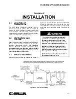
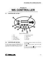
4.1
INTRODUCTION
Your new Sullair flood-lubricated rotary screw air
compressor will provide you with improved reliability
and greatly reduced maintenance.
Compared with other types of compressors, the
Sullair rotary screw is unique in mechanical
reliability, with “no wear” and “no inspection” required
of the working parts within the compressor unit.
Read
to keep your
compressor in top operating condition. Should any
questions arise which cannot be answered in the
following text, call your nearest Sullair office or the
Sullair Corporation Service Department.
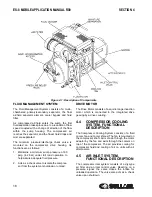
4.2
DESCRIPTION OF
COMPONENTS
Refer to
. The components and
assemblies of the ES-8 Series air compressor are
clearly shown. The complete compressor consists of
an encapsulated compressor system, inlet system,
cooling system, control system and WS control
system.
The compact design of the ES-8 Series air
compressor provides easy access to all serviceable
components.
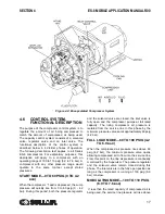
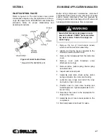
4.3
ENCAPSULATED
COMPRESSOR SYSTEM,
FUNCTIONAL DESCRIPTION
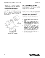
Refer to
. The encapsulated compressor
includes compressor unit, fluid management system,
and drive motor. The Sullair compressor unit is a
single-stage positive displacement lubricated type
compressor. This unit is equipped with tapered roller
bearings on the discharge and cylindrical roller
bearings on the inlet end for high load carrying
capacity. This unit provides continuous pulse-free air
compression to meet your needs. With a Sullair
compressor there will be no maintenance or internal
inspection of the compressor.
Fluid is injected into the compressor unit in large
quantities and mixes directly with the air as the rotors
turn, compressing the air. The fluid flow has three
main functions:
1. As coolant, it controls the rise of air tempera-
ture normally associated with the heat of
compression.
2. It seals the leakage paths between the rotors
and the stator and also between the rotors
themselves.
3. It acts as a lubricating film between the
rotors allowing one rotor to directly drive the
other, which is an idler.
The air/fluid mixture discharges directly into the fluid
management system.
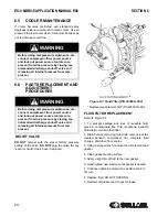
The fluid cooler bypass valve helps assure proper
cooling by directing the fluid to the fluid cooler when
discharge temperature reaches the thermostat
temperature setting.
During start-up in cool ambient conditions, the cooler
pressure drop may cause the filter bypass valve to
open up, assuring adequate fluid supply to the
compressor.
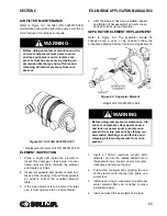
All fluid entering the compressor unit passes through
the replaceable fluid filter element. This replaceable
filter element contains a built-in bypass valve. Under
conditions of restricted flow through the element, the
bypass valve helps ensure adequate compressor
fluid flow, as well as helps prevent element failure.
WARNING
DO NOT remove caps, plugs and/or other com-
ponents when compressor is running or pres-
surized.
Stop compressor and relieve all internal pres-
sure before doing so.
Содержание 30XH
Страница 10: ...NOTES 10 ...
Страница 22: ...NOTES 22 ...
Страница 33: ...NOTES 33 ...
Страница 34: ...INLET CONTROL SEAL DRIVE GEAR AND PARTS 34 8 3 INLET CONTROL SEAL DRIVE GEAR AND PARTS ...
Страница 36: ...MOTOR COUPLING FAN AND PARTS 36 8 4 MOTOR COUPLING FAN AND PARTS ...
Страница 40: ...COMPRESSOR COOLER SYSTEM AND PARTS 40 8 6 COMPRESSOR COOLER SYSTEM AND PARTS ...
Страница 42: ...PNEUMATIC CONTROL SYSTEM AND PARTS 42 8 7 PNEUMATIC CONTROL SYSTEM AND PARTS ...
Страница 44: ...CONTROL STARTER MFV 44 8 8 CONTROL STARTER MFV ...
Страница 46: ...DECAL GROUP 46 8 9 DECAL GROUP ...
Страница 48: ...DECAL GROUP 48 8 9 DECAL GROUP CONTINUED ...
Страница 50: ...WIRING DIAGRAM FULL VOLTAGE STANDARD 50 8 10 WIRING DIAGRAM FULL VOLTAGE STANDARD ...
Страница 51: ...NOTES 51 ...


