background image

ES-8 MOBILE APPLICATION MANUAL R00

SECTION 6

26


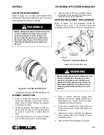
5. Reinstall the cap. Hand tighten using a

100mm maximum length, 6mm diameter pin
in the radially drilled hole. 

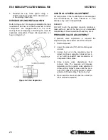
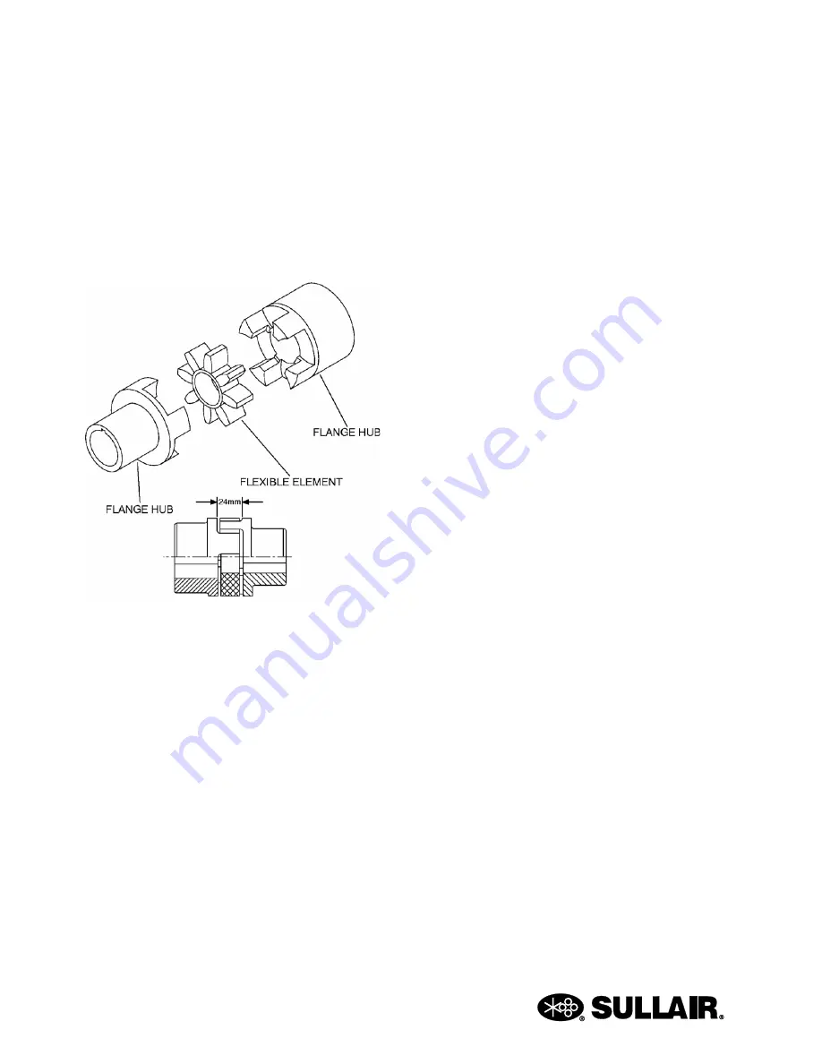
DRIVE COUPLING INSTALLATION 

Refer to 

Figure 6-4

. For coupling installation the tools

required will be one set of Allen wrenches. All ES-8
compressors are flange-mounted to the motor
making them self-aligning, eliminating the need for
alignment procedures. Proper hub separation is s
hown in 

Figure 6-4

CONTROL SYSTEM ADJUSTMENT 

All components in the Control System are designed
and manufactured to close tolerances to help
eliminate any need for adjustments. 

DANGER 

DO NOT touch the electrical contacts, terminal or
leads with any part of the body or any uninsulated
metallic object. Severe electrical shock may occur. 

PRESSURE VALVE ADJUSTMENT 

If pressure valve adjustment is required the
adjustment procedure below should be followed: 

1. Start compressor. 

2. Lower line pressure (P2) until machine goes

on load. 

3. Loosen hex nut on the regulator valve to

adjust machine modulation. Adjust screw in
or out until on load/off load modulation of
compressor takes place. 

4. Close service valve downstream from

receiver tank. The pressure will increase
depending on the regulator valve adjustment
screw setting. Adjust screw until line pres-
sure (P2) rises to the Supervisor II prepro-
grammed off load setting. Tighten hex nut. 

5. Open service valve and observe correct on

load/ off load modulation. 

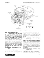
Figure 6-4: Hub Separation

Содержание 30XH

Страница 1: ...WARRANTY NOTICE PART NUMBER KEEP FOR FUTURE REFERENCE USER MANUAL SULLAIR CORPORATION The information in this manual is current as of its publication date and applies to compressor serial number and all subsequent serial numbers 02250184 779 R00 200903010000 ROTARY SCREW AIR COMPRESSOR ES 8 SERIES MOBILE APPLICATION ...

Страница 2: ...ocated at Michigan City Indiana Instruction includes training on the function and installation of Sullair service parts troubleshooting common faults and malfunctions and actual equipment operation These seminars are recommended for maintenance contractor maintenance and service personnel For detailed course outlines schedule and cost information contact SULLAIR CUSTOMER CARE TRAINING DEPARTMENT 1...

Страница 3: ...NT SECTION 2 INSTALLATION 11 2 1 LOCATION OF COMPRESSOR 11 2 2 VENTILATION AND COOLING 11 2 3 SERVICE AIR PIPING 12 2 4 COUPLING ALIGNMENT CHECK 12 2 5 FLUID LEVEL CHECK 12 2 6 MOTOR ROTATION DIRECTION CHECK 12 2 7 ELECTRICAL PREPARATION SECTION 3 SPECIFICATIONS 13 3 1 TABLE OF SPECIFICATIONS 13 3 2 COMPRESSOR SPECIFICATIONS 13 3 3 MOTOR SPECIFICATIONS 13 3 4 FLUID FILTER 13 3 5 FLUID SEPARATOR EL...

Страница 4: ...TRODUCTION 23 6 2 DAILY OPERATION 23 6 3 MOTOR BEARING LUBRICATION 23 6 4 FLUID FILTER MAINTENANCE 24 6 5 COOLER MAINTENANCE 24 6 6 PARTS REPLACEMENT AND ADJUSTMENT PROCEDURES 28 6 7 MAINTENANCE RECORD SECTION 7 TROUBLESHOOTING 29 7 1 INTRODUCTION SECTION 8 PARTS LIST 31 8 1 PROCEDURE FOR ORDERING PARTS 32 8 2 RECOMMENDED SERVICE PARTS LIST 34 8 3 INLET CONTROL SEAL DRIVE GEAR AND PARTS 36 8 4 MOT...

Страница 5: ...erein are applicable to most compressors and the concepts behind these statements are generally applicable to all compressors 1 2 PERSONAL PROTECTIVE EQUIPMENT A Prior to installing or operating the compressor owners employers and users should become familiar with and comply with all applicable OSHA regulations and or any applicable Federal State and Local codes standards and regula tions relative...

Страница 6: ...s including air line anti icer system antifreeze compound or fluid film to accumulate on under or around acoustical mate rial or on any external surfaces of the air com pressor Wipe down using an aqueous industrial cleaner or steam clean as required If necessary remove acoustical material clean all surfaces and then replace acoustical material Any acous tical material with a protective covering th...

Страница 7: ...l codes or regula tions B DO NOT use air line anti icer systems in air lines supplying respirators or other breathing air utili zation equipment and DO NOT discharge air from these systems into unventilated or other confined areas C Operate the compressor only in open or ade quately ventilated areas D Locate the compressor or provide a remote inlet so that it is not likely to ingest exhaust fumes ...

Страница 8: ...handling any ungrounded conductors 1 9 LIFTING A If the compressor is provided with a lifting bail then lift by the bail provided If no bail is provided then lift by sling Compressors to be air lifted by helicopter must not be supported by the lifting bail but by slings instead In any event lift and or handle only in full compliance with OSHA stan dards 29 CFR 1910 subpart N and or any appli cable...

Страница 9: ...ta cles at floor level and transport and corner at minimum practical speeds N Make sure pallet mounted compressors are firmly bolted or otherwise secured to the pallet prior to attempting to forklift or transport them NEVER attempt to forklift a compressor that is not secured to its pallet as uneven floors or sud den stops may cause the compressor to tumble off possibly causing serious injury or p...

Страница 10: ...NOTES 10 ...

Страница 11: ...s what is needed for service and three 3 feet 914mm or more from the compressor fluid cooler 2 3 SERVICE AIR PIPING Service air piping should be installed as shown in Figure 2 1 A shut off valve should be installed to isolate the compressor from the service line Also notice that the service line should be equipped with water legs and condensate drains throughout the system WARNING The Plastic Pipe...

Страница 12: ... If the reversed rotation is noted disconnect the power to the starter and exchange any two of the three power input leads then re check rotation A Direction of Rotation decal is located on the motor and cooler shroud to show proper motor compressor rotation 2 7 ELECTRICAL PREPARATION Interior electrical wiring is performed at the factory Required customer wiring is minimal but should be done by a...

Страница 13: ...Load Operating Pressure 60 psig 4 2 bar Maximum Full Load Operating Pressure Nameplate Pressure Bearing Type Anti friction Cooling Pressurized Fluid Lubricant see Section 3 7 Lubrication Change Recommendations Maintenance Schedule Sump Capacity 3 gallons 11 4 liters MOTOR 60 Hz Type TEFC C flange Synchronous Speed 30 HP 3600 RPM Voltage Standard All Sizes 460 Type Insulation Class B Min Maximum Am...

Страница 14: ...conditions warrant use of extended life lubricants contact Sullair for recommendation Sullair encourages the user to participate in a fluid analysis program This could result in a fluid change interval that is different from those stated in this manual 3 7 LUBRICATION CHANGE RECOMMENDATIONS MAINTENANCE SCHEDULE WARNING The Plastic Pipe Institute recommends against the use of thermoplastic pipe to ...

Страница 15: ... end for high load carrying capacity This unit provides continuous pulse free air compression to meet your needs With a Sullair compressor there will be no maintenance or internal inspection of the compressor Fluid is injected into the compressor unit in large quantities and mixes directly with the air as the rotors turn compressing the air The fluid flow has three main functions 1 As coolant it c...

Страница 16: ...luid pressure 2 Acts as a check valve to isolate the compres sor from the system at shutdown or unload DRIVE MOTOR The Drive Motor consists of a squirrel cage induction motor which is connected to the integrated drive gearing by a drive coupling 4 4 COMPRESSOR COOLING SYSTEM FUNCTIONAL DESCRIPTION The Compressor Cooling System consists of a fluid cooler fan and cooler shroud The fan is mounted on ...

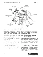
Страница 17: ...e will quickly rise from 0 to 60 psig 0 4 2 bar During this period both the pressure regulator and the solenoid valve are closed the inlet valve is fully open and the compressor pumps at full rated capacity The rising compressor air pressure is isolated from the service line in this phase by the minimum pressure valve set at approximately 60 psig 4 2 bar FULL LOAD MODE 60 TO 100 PSIG 4 2 TO 6 9 BA...

Страница 18: ...be supplied directly to close the inlet valve Simultaneously the solenoid valve sends a pneumatic signal to the blowdown valve The blowdown valve opens the sump to the atmosphere reducing the sump pressure to approximately 20 to 30 psig 1 4 to 2 1 bar The check valve in the air service line prevents line pressure from returning to the sump When the line pressure drops to the low setting cut in pre...

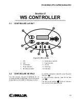
Страница 19: ...s two main pads for compressor control To start the compressor operation press the green Start pad To stop compressor operation press the red Stop pad The Run mode indicator lights up whenever the control is in an operating mode 6 1 7 2 8 3 9 4 10 5 Figure 5 1 WS Controller 1 ON 2 OFF 3 LCD Display 4 Power Indicator 5 Run Mode Indicator 6 Maintenance Indicator 7 Fault Indicator 8 Up Key 9 Down Key...

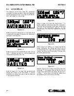
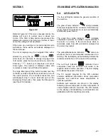
Страница 20: ...service instructions to correct the cause Press the Stop pad to reset the controller Figure 5 5 Refer to Figure 5 6 Press the Down arrow to display additional information about the compressor The upper line will indicate Compressor Status and the name of the temperature pressure or other measurement The lower line indicates the present reading Figure 5 6 Refer to Figure 5 7 When you continue beyon...

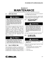
Страница 21: ... The four LED lights indicate the general condition of the machine The green Power indicator simply indicates that power is applied to the controller It will blink very slowly if the WS Controller is set up to automatically restart after power failure The green Run mode indicator indicates compressor operation is enabled It lights steadily if the motor is running If the motor stops while in Automa...

Страница 22: ...NOTES 22 ...

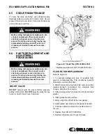
Страница 23: ...e a general check of the overall compressor should bemade to assure that the compressor is running properly 6 3 MOTOR BEARING LUBRICATION See motor manufacturer s lubrication instructions 6 4 FLUID FILTER MAINTENANCE Replace the fluid filter element under any of the following conditions 1 As recommended in the Lubrication Guide in the Specification Section and below 2 Every year 3 Every fluid chan...

Страница 24: ...ange drain fluid from cooler 3 Using a strap wrench remove the old element and gasket 4 Clean gasket seating surface 5 Apply a light film of fluid to the new gasket 6 Hand tighten new element until gasket is seated 7 Continue tightening element an additional 1 2 to 3 4 turn 8 Replace fluid DO NOT OVERFILL 9 Restart compressor and check for leaks WARNING Before doing compressor maintenance dis conn...

Страница 25: ... for element replacement 1 Insert a 100mm maximum length 6mm diameter pin into the radially drilled hole in the separator cap Loosen unscrew counter clockwise and remove the cap 2 Pull out the old element by gripping the end of the element with channel lock pliers or a similar tool 3 Install new o rings on separator cap and sep arator element filter and oil lightly to make installation easier 4 In...

Страница 26: ...touch the electrical contacts terminal or leads with any part of the body or any uninsulated metallic object Severe electrical shock may occur PRESSURE VALVE ADJUSTMENT If pressure valve adjustment is required the adjustment procedure below should be followed 1 Start compressor 2 Lower line pressure P2 until machine goes on load 3 Loosen hex nut on the regulator valve to adjust machine modulation ...

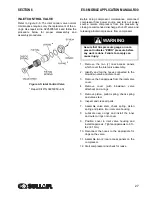
Страница 27: ...the blowdown valve and disconnect 3 Remove the 3 capscrews from the inlet valve cover 4 Remove cover with blowdown valve attached and o rings 5 Remove piston piston spring check spring and valve stem 6 Inspect and clean all parts 7 Assemble valve stem check spring piston spring and piston into inlet valve housing 8 Lubricate new o rings and install the inner and outer o rings onto cover 9 Position...

Страница 28: ...NOTES 28 6 7 MAINTENANCE RECORD Model No Serial No Date Hourmeter Maintenance Performed Work Performed By Authorized By ...

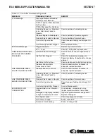
Страница 29: ... burnt odor Should your problem persist after making the recommended check consult your nearest Sullair representative or the Sullair Corporation factory Table 7 1 Controller Troubleshooting Guide MESSAGE PROBABLE CAUSE REMEDY T1 HI Message Discharge Temperature Exceeded 225 F 107 C for Pre Alarm Discharge Temperature Exceeded 235 F 113 C for Shutdown Ambient temperature exceeded 105 F 41 C Improv...

Страница 30: ... Fully Open Check actuation and butterfly disc position Pressure Sensor and or Connections at Fault Check connections from transducer If adequate replace transducer LINE PRESSURE RISES ABOVE UNLOAD SETTING Pressure Sensor P2 at Fault Check connections from transducer If adequate replace transducer Unloading Device i e Blowdown Valve Inlet Valve Failed to Operate Check operation of unloading device...

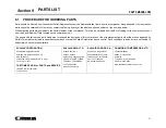
Страница 31: ...by Sullair Corporation may lead to hazardous conditions over which Sullair Corporation has no control Such conditions include but are not limited to bodily injury and compressor failure SULLAIR CORPORATION 3700 East Michigan Boulevard Michigan City Indiana 46360 U S A www sullair com Telephone 1 800 SULLAIR U S A only Fax 219 874 1273 CUSTOMER CARE for PARTS and SERVICE 1 888 SULLAIR 785 5247 219 ...

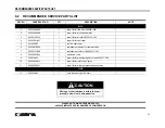
Страница 32: ...6 02250078 204 1 replacement element for thermal valve 7 02250157 500 1 replacement kit for coil 02250157 502 8 02250049 634 1 blowdown valve 9 250019 453 1 repair kit for pressure regulator valve 250017 280 10 02250050 614 1 repair kit for inlet control valve 11 02250050 612 1 repair kit for minimum pressure check valve FLUID 12 250022 669 1 fluid Sullube 5 gal 19 liter Continued on next page PLE...

Страница 33: ...NOTES 33 ...

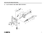
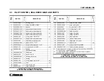
Страница 34: ...INLET CONTROL SEAL DRIVE GEAR AND PARTS 34 8 3 INLET CONTROL SEAL DRIVE GEAR AND PARTS ...

Страница 35: ... 210 1 bearing 20 826502 152 1 o ring viton 3 1 4 x 3 32 II 21 02250133 494 1 seal II 22 026397 1 shim set 3 5 x 3 0 23 250035 254 1 cover shaft seal PLEASE NOTE WHEN ORDERING PARTS INDICATE SERIAL NUMBER OF COMPRESSOR 24 829308 020 7 capscrew M8 x 20MM 25 02250119 254 1 cover inlet control 26 826502 235 1 o ring viton 3 x 3 32 27 826502 226 1 o ring viton 2 x 1 8 28 02250048 909 1 piston inlet va...

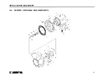
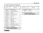
Страница 36: ...MOTOR COUPLING FAN AND PARTS 36 8 4 MOTOR COUPLING FAN AND PARTS ...

Страница 37: ...x 40MM 13 865712 370 2 washer 12MM 14 825912 175 2 nut M12 x 1 75 15 865406 125 1 washer 8MM 16 828008 016 1 capscrew 8MM x 16MM 17 865712 370 1 washer 12MM 18 825912 175 1 nut hex M12 x 1 75 19 02250047 047 1 isolator vibration 75MM x 50MM optional 20 846500 125 1 elbow 45 liq tite 1 1 4 not shown 21 847006 040 2 washer conduit red 1 1 2 1 not shown 22 02250049 159 1 spacer shaft 30 HP 23 0225012...

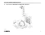
Страница 38: ...INLET FILTER COMPRESSOR HOUSING SUMP AND PARTS 38 8 5 INLET FILTER COMPRESSOR HOUSING SUMP AND PARTS 02250170 953 ...

Страница 39: ...5 1 FITTING COMPRESS ADJ 20 250039 359 1 PLUG E6E OIL FILL HX HD1 1 16 21 811506 075 1 ADAPTER FEMALE PIPE 3 4 X 3 4 22 825920 250 1 NUT HEX METRIC M20 X 2 5 PLEASE NOTE WHEN ORDERING PARTS INDICATE SERIAL NUMBER OF COMPRESSOR 23 826502 235 1 O RING VITON 3 1 8 X 1 8 24 829308 060 3 SCRW SOC ISO 4762 M8 X 60MM 25 829316 060 4 SCRW SOC ISO 4762 M16 X 60MM 26 829316 100 16 SCRW SOC ISO 4762 M16 X 10...

Страница 40: ...COMPRESSOR COOLER SYSTEM AND PARTS 40 8 6 COMPRESSOR COOLER SYSTEM AND PARTS ...

Страница 41: ...PT CLR ASSY ES8 SHOVEL PKG 9 250040 092 1 AFTERCOOLER 8E 10 825906 100 10 NUT HEX METRIC M6 X 1 0 11 825908 125 3 NUT HEX METRIC M8 X 1 25 12 829306 012 7 SCRW SOC ISO 4762 M6 X 12MM 13 829306 020 20 SCRW SOC ISO 4762 M6 X 20MM 14 829308 016 3 SCRW SOC ISO 4762 M8 X 16MM 15 829308 030 3 SCRW SOC ISO 4762 M8 X 30MM 16 838806 160 36 WASHER SPR LOCK METRIC PLTD M6 17 838808 200 9 WASHER SPR LOCK METR...

Страница 42: ...PNEUMATIC CONTROL SYSTEM AND PARTS 42 8 7 PNEUMATIC CONTROL SYSTEM AND PARTS ...

Страница 43: ...PKG 6 241771 1 STRAINER V TYPE 300PSIX1 4 7 250017 280 1 VALVE PRESSURE REGULATOR 8 250018 430 2 ELBOW 1 4 TUBE X 1 4 NPT 9 408893 1 VALVE SHUTTLE 1 4 DBL CHK 10 841500 004 2 BULKHEAD PIPE 1 4 NPT 11 847815 050 2 NIPPLE CHASE COND 1 2 12 860104 025 4 CONN 37 FL MPT PLTD 1 4 X 1 4 13 860204 025 9 ELBOW 37FL 90M 1 4 X 1 4 14 860404 025 4 NIPPLE PIPE HEX 1 4 X 1 4 15 866815 010 2 TEE PIPE 150 PLT 1 4...

Страница 44: ...CONTROL STARTER MFV 44 8 8 CONTROL STARTER MFV ...

Страница 45: ...02250085 504 E22LLB2 1 SW PB OPER RED40MM PUSH TWIST 11 250027 125 E22BF1 1 BLOCK CONTACT 1 N C 12 02250081 473 E22VA2 1 NPL YELLOW RING 45MM E STOP 13 02250159 547 1 RCPT S4 PROGRAM PORT NEMA 6P 14 02250159 549 1 CAP S4 PROGRAM PORT NEMA 6P 15 02250145 195 1423553 1 BLK POWER DISTRIBUTION 175A PLEASE NOTE WHEN ORDERING PARTS INDICATE SERIAL NUMBER OF COMPRESSOR 16 02250167 849 XTCEXFBG11 1 BLK AU...

Страница 46: ...DECAL GROUP 46 8 9 DECAL GROUP ...

Страница 47: ...sor fluid fill cap 2 49850 1 sign danger electrocution 3 407408 1 sign warning hot surfaces 4 41065 1 decal warning auto start 5 250027 935 1 decal danger breath air 6 250003 144 1 sign warning food grade lube 7 250021 564 1 decal rotation direction PLEASE NOTE WHEN ORDERING PARTS INDICATE SERIAL NUMBER OF COMPRESSOR ...

Страница 48: ...DECAL GROUP 48 8 9 DECAL GROUP CONTINUED ...

Страница 49: ...d 02250075 045 1 decal protective earth ground not shown 02250075 540 1 decal PE designation not shown 9 42218 1 decal danger hi voltage 10 49852 1 sign warning ground fault 11 02250059 288 1 decal ISO 9001 12 02250055 510 1 decal warning lift PLEASE NOTE WHEN ORDERING PARTS INDICATE SERIAL NUMBER OF COMPRESSOR ...

Страница 50: ...WIRING DIAGRAM FULL VOLTAGE STANDARD 50 8 10 WIRING DIAGRAM FULL VOLTAGE STANDARD ...

Страница 51: ...NOTES 51 ...

Страница 52: ...ssors LTD Princes Highway Hallam Victoria 3803 Australia Telephone 61 3 9703 8000 Fax 61 3 9703 8053 www championcompressors com au SULLAIR CORPORATION 3700 East Michigan Boulevard Michigan City Indiana 46360 U S A www sullair com Telephone 1 800 SULLAIR U S A only Fax 219 874 1273 CUSTOMER CARE for PARTS and Service 1 888 SULLAIR 7855247 219 874 1835 SULLAIR EUROPE S A Zone Des Granges BP 82 4260...

Отзывы: