


Section 5
MAINTENANCE
32
concerning the trouble should be systematically
analyzed before undertaking any repairs or compo-
nent replacement procedures.
A detailed visual inspection is worth performing for
almost all problems. Doing so may prevent unnec-
essary additional damage to the compressor.
Always remember to:
1. Check for loose wiring.
2. Check for damaged piping.
3. Check for parts damaged by heat or an electrical
short circuit, usually apparent by discoloration or
a burnt odor.
Should the problem(s) persist after making the rec-
ommended check, consult your nearest Sullair rep-
resentative or the Sullair Corporation.
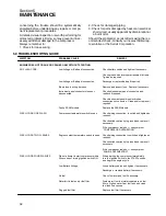
5.9 TROUBLESHOOTING GUIDE
SYMPTOM
PROBABLE CAUSE
REMEDY
ENGINE DOES NOT CRANK OR CRANKS ONLY WITHOUT STARTING:
NO FLASH CODE:
Low Voltage or Battery disconnected
Check battery cables and tighten if necessary.
Check ground wire for proper attachment to frame.
Tighten as required.
Low Voltage or Battery disconnected
Recharge or replace battery if required.
Blown fuse in wiring harness
Remove and inspect fuse. Replace if necessary.
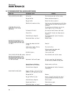
Instrument panel connectors loose or
Checked instrument panel connectors and
disconnected
reattach if required.
Check instrument panel wires for broken
connections or corrosion. Clean and/or replace if
required
Faulty SSAM module
Replace the SSAM Module.
FLASH CODE: ONE FLASH
Compressor temperature switch is open
Check wiring connection to switch and tighten as
required.
Check switch continuity to ground and replace if
necessary.
If the compressor feels hot --- see symptom
“COMPRESSOR OVERHEATING”.
FLASH CODE: TWO FLASHES
Engine coolant temperature switch is open
Check wiring connection to switch and tighten as
required.
Check switch continuity to ground and replace if
necessary.
If the compressor feels hot --- see symptom
“ENGINE OVERHEATING”.
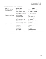
FLASH CODE: FOUR FLASHES
Did not attempt to start compressor within
When starting the compressor, immediately
30 seconds of turning ignition switch ON.
turn the Ignition Switch to the START position
and begin the engine cycle.
Low Battery Voltage
Loose battery cables and tighten if necesssary.
Recharge or replace battery if necessary.
No fuel
Check fuel level and fuel if necessary.
Water/dirt in fuel and/or fuel filter
Drain water from fuel water separators on fuel
filters. Siphon water from fuel tank and clean
fuel tank if necessary.
Plugged fuel filter
Replace fuel filter if necessary.
Содержание 185H
Страница 6: ......
Страница 14: ...8 NOTES...
Страница 19: ...Section 2 DESCRIPTION 13 Figure 2 4A Control System with Piping and Instrumentation 185H 210H Models...
Страница 20: ...Section 2 DESCRIPTION 14 Figure 2 4B Control System with Piping and Instrumentation 260 Models...
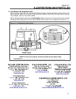
Страница 23: ...Section 2 DESCRIPTION 17 Figure 2 6 Instrument Panel Group...
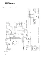
Страница 24: ...Section 2 DESCRIPTION 18 Figure 2 7 Electrical System JOHN DEERE 02250144 446R05...
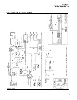
Страница 25: ...Section 2 DESCRIPTION 19 Figure 2 7A Electrical System CATERPILLAR P02250144 395R04...
Страница 26: ...20 NOTES...
Страница 30: ...24 NOTES...
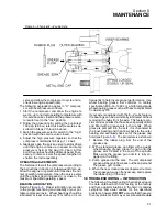
Страница 36: ...Section 5 MAINTENANCE 30 Figure 5 4 Control System Adjustment 185H 210 MODELS 260 MODELS...
Страница 42: ...36 NOTES...
Страница 49: ...Section 7 ILLUSTRATIONS AND PARTS LIST 43 NOTES...
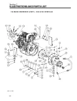
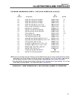
Страница 50: ...Section 7 ILLUSTRATIONS AND PARTS LIST 44 7 3A ENGINE COMPRESSOR PARTS 185H 210H CATERPILLAR 02250149 637R02...
Страница 52: ...Section 7 ILLUSTRATIONS AND PARTS LIST 46 7 3A ENGINE COMPRESSOR PARTS 185H 210H CATERPILLAR 02250149 637R02...
Страница 54: ...Section 7 ILLUSTRATIONS AND PARTS LIST 48 7 3B ENGINE COMPRESSOR PARTS 260 CATERPILLAR 02250149 631R02...
Страница 56: ...Section 7 ILLUSTRATIONS AND PARTS LIST 50 7 3B ENGINE COMPRESSOR PARTS 260 CATERPILLAR 02250149 631R02...
Страница 58: ...Section 7 ILLUSTRATIONS AND PARTS LIST 52 7 3C ENGINE COMPRESSOR PARTS 185H 210H JOHN DEERE 02250149 639R02...
Страница 60: ...Section 7 ILLUSTRATIONS AND PARTS LIST 54 7 3C ENGINE COMPRESSOR PARTS 185H 210H JOHN DEERE 02250149 639R02...
Страница 62: ...Section 7 ILLUSTRATIONS AND PARTS LIST 56 7 3D ENGINE COMPRESSOR PARTS 260 JOHN DEERE 02250149 634R02...
Страница 64: ...Section 7 ILLUSTRATIONS AND PARTS LIST 58 7 3D ENGINE COMPRESSOR PARTS 260 JOHN DEERE continued 02250149 634R02...
Страница 66: ...Section 7 ILLUSTRATIONS AND PARTS LIST 60 7 4A AIR INLET AND EXHAUST ALL CATERPILLAR MODELS 02250149 632R00...
Страница 68: ...Section 7 ILLUSTRATIONS AND PARTS LIST 62 7 4B AIR INLET AND EXHAUST ALL JOHN DEERE MODELS 02250149 636R00...
Страница 76: ...Section 7 ILLUSTRATIONS AND PARTS LIST 70 7 7A FRAME RUNNING GEAR PARTS ALL MODELS 02250155 667R00...
Страница 78: ...Section 7 ILLUSTRATIONS AND PARTS LIST 72 7 7A FRAME RUNNING GEAR PARTS ALL MODELS 02250155 667R00...
Страница 80: ...Section 7 ILLUSTRATIONS AND PARTS LIST 74 7 7B FRAME LESS RUNNING GEAR PARTS ALL MODELS 02250151 314R00...
Страница 82: ...Section 7 ILLUSTRATIONS AND PARTS LIST 76 7 7B FRAME LESS RUNNING GEAR PARTS ALL MODELS 02250151 314R00...
Страница 84: ...Section 7 ILLUSTRATIONS AND PARTS LIST 78 7 8 DISCHARGE SYSTEM AND PARTS ALL MODELS 02250149 638R01...
Страница 86: ...Section 7 ILLUSTRATIONS AND PARTS LIST 80 7 8 DISCHARGE SYSTEM AND PARTS ALL MODELS 02250149 638R01...
Страница 90: ...Section 7 ILLUSTRATIONS AND PARTS LIST 84 7 10 ELECTRICAL PARTS ALL MODELS 02250148 897R00...
Страница 92: ...Section 7 ILLUSTRATIONS AND PARTS LIST 86 7 11A FUEL TANK AND PARTS ALL CATERPILLAR MODELS 02250148 847R01...
Страница 94: ...Section 7 ILLUSTRATIONS AND PARTS LIST 88 7 11B FUEL TANK AND PARTS ALL JOHN DEERE MODELS 02250149 635R01...
Страница 96: ...Section 7 ILLUSTRATIONS AND PARTS LIST 90 7 12 CANOPY ACOUSTICAL PANELS PARTS ALL MODELS 02250151 313R00...
Страница 98: ...Section 7 ILLUSTRATIONS AND PARTS LIST 92 7 12 CANOPY ACOUSTICAL PANELS PARTS ALL MODELS 02250151 313R00...
Страница 112: ...Section 7 ILLUSTRATIONS AND PARTS LIST 106 7 14F INSTRUMENT PANEL AND PARTS 260 CATERPILLAR FULL GAUGE 02250154 338R02...
Страница 116: ...Section 7 ILLUSTRATIONS AND PARTS LIST 110 7 14H INSTRUMENT PANEL AND PARTS 260 JOHN DEERE FULL GAUGE 02250154 443R02...
Страница 118: ...Section 7 ILLUSTRATIONS AND PARTS LIST 112 7 15 SINGLE HOSE REEL OPTION ALL MODELS 02250151 192R01...
Страница 120: ...Section 7 ILLUSTRATIONS AND PARTS LIST 114 7 16 DUAL HOSE REEL OPTION ALL MODELS 02250141 690R02...
Страница 122: ...Section 7 ILLUSTRATIONS AND PARTS LIST 116 7 17 ONE PINT OILER OPTION ALL MODELS 02250151 189R00...
Страница 124: ...Section 7 ILLUSTRATIONS AND PARTS LIST 118 7 18 ONE QUART OILER MOISTURE SEPARATOR OPTIONS ALL MODELS 02250151 191R00...
Страница 126: ...Section 7 ILLUSTRATIONS AND PARTS LIST 120 7 19 CANADIAN TAIL CLEARANCE LIGHTS ALL MODELS 02250150 874R00...
Страница 128: ...Section 7 ILLUSTRATIONS AND PARTS LIST 122 7 20 DECALS...
Страница 130: ...Section 7 ILLUSTRATIONS AND PARTS LIST 124 7 20 DECALS...
Страница 132: ...Section 7 ILLUSTRATIONS AND PARTS LIST 126 7 20 DECALS...
Страница 134: ...Section 7 ILLUSTRATIONS AND PARTS LIST 128 7 20 DECALS...
Страница 136: ...Section 7 ILLUSTRATIONS AND PARTS LIST 130 7 20 DECALS...
Страница 138: ...Section 7 ILLUSTRATIONS AND PARTS LIST 132 7 21 DECAL LOCATIONS 02250149 633R01...
Страница 140: ...Section 7 ILLUSTRATIONS AND PARTS LIST 134 7 22 DRAWBAR INSTALLATION ALL MODELS 02250141 874R00...
Страница 142: ......
Страница 143: ......


