


Section 4
OPERATION
25
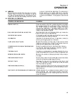
4.1 GENERAL
While Sullair has built into this compressor a compre-
hensive array of controls and indicators to assure
you that it is operating properly, you will want to rec-
ognize and interpret the reading which will call for
service or indicate the beginning of a malfunction.
Before starting your Sullair compressor, read this
section thoroughly and familiarize yourself with the
controls and indicators --- their purpose, location and
use.
4.2 PURPOSE OF CONTROLS
CONTROL OR INDICATOR
PURPOSE
ENGINE SWITCH
Press this switch to the “ ON” (ignition) position to energize
the electrical system of the compressor. Press the switch to
the “START” position to momentarily engage the starter
and start the compressor. Pressthe switch to the “OFF”
position to shut the compressor down. This switch is lo-
cated on the instrument panel.
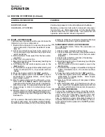
COLD WEATHER STARTING AID BUTTON
Push this button, prior to compressor start---up, to allow the
engine to warm---up for easy starting.
AIR PRESSURE GAUGE
Continually monitors the pressure inside the receiver sump
at various load and unload conditions.
HOURMETER
Indicates the accumulated hours of operation. Useful for
planning and logging service schedules.
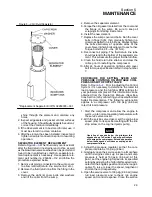
FLUID LEVEL SIGHT GLASS
Monitors the fluid level in the sump. Proper level is visible
halfway up the sight glass. Check the level when the com-
pressor is shut down and on level ground.
COMPRESSOR DISCHARGE TEMPERATURE
Opens the electrical circuit to shut down the compres---
SWITCH
sor when the discharge temperature reaches a specific
value (see Section 3, Specifications).
THERMAL VALVE
Functions as a temperature regulator directing the com-
pressor fluid either to the cooler or to the compressor unit.
MINIMUM PRESSURE DEVICE
Maintains the minimum of 85 psig (5.9 bar) in the compres-
sor sump.
PRESSURE RELIEF VALVE
Opens sump pressure to the atmosphere should pressure
inside the sump exceed 200 psig (13.8 bar) .
AIR INLET VALVE
Regulates the amount of air allowed to enter the air inlet
valve. This regulation is determined by a pressure signal
from the pressure regulator.
PRESSURE REGULATOR (S)
Allows a pressure signal to reach the engine speed control
cylinder and the air inlet valve to control air delivery accord-
ing to demand.
SHUTDOWN SYSTEM/ANNUNCIATOR MODULE (SSAM) Monitors the compressor safety system for shut-
down conditions. The annunciator module on the instru-
ment panel will flash a code indicating the reason for com-
pressor shutdown.
Содержание 185H
Страница 6: ......
Страница 14: ...8 NOTES...
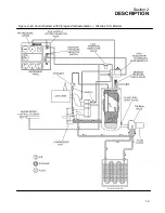
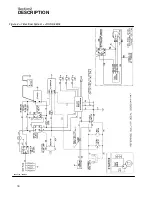
Страница 19: ...Section 2 DESCRIPTION 13 Figure 2 4A Control System with Piping and Instrumentation 185H 210H Models...
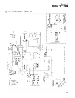
Страница 20: ...Section 2 DESCRIPTION 14 Figure 2 4B Control System with Piping and Instrumentation 260 Models...
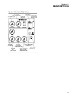
Страница 23: ...Section 2 DESCRIPTION 17 Figure 2 6 Instrument Panel Group...
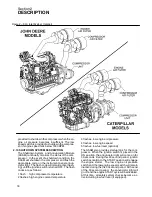
Страница 24: ...Section 2 DESCRIPTION 18 Figure 2 7 Electrical System JOHN DEERE 02250144 446R05...
Страница 25: ...Section 2 DESCRIPTION 19 Figure 2 7A Electrical System CATERPILLAR P02250144 395R04...
Страница 26: ...20 NOTES...
Страница 30: ...24 NOTES...
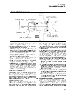
Страница 36: ...Section 5 MAINTENANCE 30 Figure 5 4 Control System Adjustment 185H 210 MODELS 260 MODELS...
Страница 42: ...36 NOTES...
Страница 49: ...Section 7 ILLUSTRATIONS AND PARTS LIST 43 NOTES...
Страница 50: ...Section 7 ILLUSTRATIONS AND PARTS LIST 44 7 3A ENGINE COMPRESSOR PARTS 185H 210H CATERPILLAR 02250149 637R02...
Страница 52: ...Section 7 ILLUSTRATIONS AND PARTS LIST 46 7 3A ENGINE COMPRESSOR PARTS 185H 210H CATERPILLAR 02250149 637R02...
Страница 54: ...Section 7 ILLUSTRATIONS AND PARTS LIST 48 7 3B ENGINE COMPRESSOR PARTS 260 CATERPILLAR 02250149 631R02...
Страница 56: ...Section 7 ILLUSTRATIONS AND PARTS LIST 50 7 3B ENGINE COMPRESSOR PARTS 260 CATERPILLAR 02250149 631R02...
Страница 58: ...Section 7 ILLUSTRATIONS AND PARTS LIST 52 7 3C ENGINE COMPRESSOR PARTS 185H 210H JOHN DEERE 02250149 639R02...
Страница 60: ...Section 7 ILLUSTRATIONS AND PARTS LIST 54 7 3C ENGINE COMPRESSOR PARTS 185H 210H JOHN DEERE 02250149 639R02...
Страница 62: ...Section 7 ILLUSTRATIONS AND PARTS LIST 56 7 3D ENGINE COMPRESSOR PARTS 260 JOHN DEERE 02250149 634R02...
Страница 64: ...Section 7 ILLUSTRATIONS AND PARTS LIST 58 7 3D ENGINE COMPRESSOR PARTS 260 JOHN DEERE continued 02250149 634R02...
Страница 66: ...Section 7 ILLUSTRATIONS AND PARTS LIST 60 7 4A AIR INLET AND EXHAUST ALL CATERPILLAR MODELS 02250149 632R00...
Страница 68: ...Section 7 ILLUSTRATIONS AND PARTS LIST 62 7 4B AIR INLET AND EXHAUST ALL JOHN DEERE MODELS 02250149 636R00...
Страница 76: ...Section 7 ILLUSTRATIONS AND PARTS LIST 70 7 7A FRAME RUNNING GEAR PARTS ALL MODELS 02250155 667R00...
Страница 78: ...Section 7 ILLUSTRATIONS AND PARTS LIST 72 7 7A FRAME RUNNING GEAR PARTS ALL MODELS 02250155 667R00...
Страница 80: ...Section 7 ILLUSTRATIONS AND PARTS LIST 74 7 7B FRAME LESS RUNNING GEAR PARTS ALL MODELS 02250151 314R00...
Страница 82: ...Section 7 ILLUSTRATIONS AND PARTS LIST 76 7 7B FRAME LESS RUNNING GEAR PARTS ALL MODELS 02250151 314R00...
Страница 84: ...Section 7 ILLUSTRATIONS AND PARTS LIST 78 7 8 DISCHARGE SYSTEM AND PARTS ALL MODELS 02250149 638R01...
Страница 86: ...Section 7 ILLUSTRATIONS AND PARTS LIST 80 7 8 DISCHARGE SYSTEM AND PARTS ALL MODELS 02250149 638R01...
Страница 90: ...Section 7 ILLUSTRATIONS AND PARTS LIST 84 7 10 ELECTRICAL PARTS ALL MODELS 02250148 897R00...
Страница 92: ...Section 7 ILLUSTRATIONS AND PARTS LIST 86 7 11A FUEL TANK AND PARTS ALL CATERPILLAR MODELS 02250148 847R01...
Страница 94: ...Section 7 ILLUSTRATIONS AND PARTS LIST 88 7 11B FUEL TANK AND PARTS ALL JOHN DEERE MODELS 02250149 635R01...
Страница 96: ...Section 7 ILLUSTRATIONS AND PARTS LIST 90 7 12 CANOPY ACOUSTICAL PANELS PARTS ALL MODELS 02250151 313R00...
Страница 98: ...Section 7 ILLUSTRATIONS AND PARTS LIST 92 7 12 CANOPY ACOUSTICAL PANELS PARTS ALL MODELS 02250151 313R00...
Страница 112: ...Section 7 ILLUSTRATIONS AND PARTS LIST 106 7 14F INSTRUMENT PANEL AND PARTS 260 CATERPILLAR FULL GAUGE 02250154 338R02...
Страница 116: ...Section 7 ILLUSTRATIONS AND PARTS LIST 110 7 14H INSTRUMENT PANEL AND PARTS 260 JOHN DEERE FULL GAUGE 02250154 443R02...
Страница 118: ...Section 7 ILLUSTRATIONS AND PARTS LIST 112 7 15 SINGLE HOSE REEL OPTION ALL MODELS 02250151 192R01...
Страница 120: ...Section 7 ILLUSTRATIONS AND PARTS LIST 114 7 16 DUAL HOSE REEL OPTION ALL MODELS 02250141 690R02...
Страница 122: ...Section 7 ILLUSTRATIONS AND PARTS LIST 116 7 17 ONE PINT OILER OPTION ALL MODELS 02250151 189R00...
Страница 124: ...Section 7 ILLUSTRATIONS AND PARTS LIST 118 7 18 ONE QUART OILER MOISTURE SEPARATOR OPTIONS ALL MODELS 02250151 191R00...
Страница 126: ...Section 7 ILLUSTRATIONS AND PARTS LIST 120 7 19 CANADIAN TAIL CLEARANCE LIGHTS ALL MODELS 02250150 874R00...
Страница 128: ...Section 7 ILLUSTRATIONS AND PARTS LIST 122 7 20 DECALS...
Страница 130: ...Section 7 ILLUSTRATIONS AND PARTS LIST 124 7 20 DECALS...
Страница 132: ...Section 7 ILLUSTRATIONS AND PARTS LIST 126 7 20 DECALS...
Страница 134: ...Section 7 ILLUSTRATIONS AND PARTS LIST 128 7 20 DECALS...
Страница 136: ...Section 7 ILLUSTRATIONS AND PARTS LIST 130 7 20 DECALS...
Страница 138: ...Section 7 ILLUSTRATIONS AND PARTS LIST 132 7 21 DECAL LOCATIONS 02250149 633R01...
Страница 140: ...Section 7 ILLUSTRATIONS AND PARTS LIST 134 7 22 DRAWBAR INSTALLATION ALL MODELS 02250141 874R00...
Страница 142: ......
Страница 143: ......


