


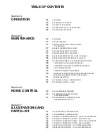

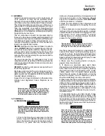


Section 1
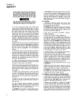
SAFETY
4
J.
Keep personnel out of line with and away from
the discharge opening of hoses, tools or other
points of compressed air discharge.
K. DO NOT
use air at pressures higher than 30
psig (2.1 bar) for cleaning purposes, and then only
with effective chip guarding and personal protec-
tive equipment per OSHA Standard 29 CFR
1910.242 (b) or any applicable Federal, State and
Local codes, standards and regulations.
L. DO NOT
engage in horseplay with air hoses as
death or serious injury may result.
M.
This equipment is supplied with an ASME de-
signed pressure vessel protected by an ASME
rated relief valve. Lift the handle once a week to
make sure the valve is functional.
DO NOT
lift the
handle while machine is under pressure.
N.
If the machine is installed in an enclosed area it is
necessary to vent the relief valve to the outside of
the structure or to an area of non---exposure.
O. DO NOT
remove radiator filler cap until the cool-
ant temperature is below its boiling point. Then
loosen cap slowly to its stop to relieve any excess
pressure and make sure coolant is not boiling be-
fore removing cap completely. Remove radiator
filler cap only when cool enough to touch with a
bare hand.
P.
The ethyl ether in the replaceable cylinders used
in diesel ether starting aid systems (optional) is un-
der pressure.
DO NOT
puncture or incinerate
those cylinders.
DO NOT
attempt to remove the
center valve core or side pressure relief valve from
these cylinders regardless of whether they are full
or empty.
Q.
If a manual blowdown valve is provided on the
receiver, open the valve to insure all internal pres-
sure has been vented prior to servicing any pres-
surized component of the compressor air/fluid sys-
tem.
1.4 FIRE AND EXPLOSION
A.
Refuel at a service station or from a fuel tank de-
signed for its intended purpose. If this is not possi-
ble, ground the compressor to the dispenser prior
to refueling.
B.
Clean up spills of fuel, fluid, battery electrolyte or
coolant immediately if such spills occur.
C.
Shut off air compressor and allow it to cool.
Then keep sparks, flames and other sources of ig-
nition away and
DO NOT
permit smoking in the vi-
cinity when adding fuel, or when checking or add-
ing electrolyte to batteries, or when checking or
adding fluid, or when checking diesel engine ether
starting aid systems or replacing cylinders, or
when refilling air line anti---icer systems antifreeze
compound.
D. DO NOT
permit liquids, including air line anti---
icer system antifreeze compound or fluid film to ac-
cumulate on bottom covers or on, under or around
acoustical material, or on any external or internal
surfaces of the air compressor. Wipe down using
an aqueous industrial cleaner or steam clean as re-
quired. If necessary remove acoustical material,
clean all surfaces and then replace acoustical ma-
terial. Any acoustical material with a protective cov-
ering that has been torn or punctured should be re-
placed immediately to prevent accumulation of liq-
uids or fluid film within the material
. DO NOT
use
flammable solvents for cleaning purposes.
E.
Disconnect the grounded (negative) battery
connection prior to attempting any repairs or clean-
ing inside the enclosure. Tag the battery connec-
tions so others will not unexpectedly reconnect it.
F.
Keep electrical wiring, including the battery ter-
minals and other terminals, in good condition. Re-
place any wiring that has cracked, cut abraded or
otherwise degraded insulation or terminals that are
worn, discolored or corroded. Keep all terminals
clean and tight.
G.
Turn off battery charger before making or break-
ing connections to the battery.
H.
Keep grounded conductive objects such as
tools away from exposed live electrical parts such
as terminals to avoid arcing which might serve as a
source of ignition.
I.
Replace damaged fuel tanks or lines immediately
rather than attempt to weld or otherwise repair
them.
DO NOT
store or attempt to operate the
compressor with any known leaks in the fuel sys-
tem. Tag the compressor and render it inoperative
until repair can be made.
J.
Remove any acoustical material or other material
that may be damaged by heat or that may support
combustion prior to attempting weld repairs. Re-
move diesel engine ether starting aid cylinders and
air line anti---icer system components containing
antifreeze compound, prior to attempting weld re-
pairs in any place other than the fuel system.
DO
NOT
weld on or near the fuel system.
K.
Keep a suitable fully charged class BC or ABC
fire extinguisher or extinguishers nearby when
servicing and operating the compressor.
L.
Keep oily rags, trash, leaves, litter or other com-
bustibles out of and away from the compressor.
M.
Open all access doors and allow the enclosure
to ventilate thoroughly prior to attempting to start
the engine.
N. DO NOT
operate compressor under low over-
hanging leaves or permit such leaves to contact hot
exhaust system surfaces when operating the com-
pressor in forested areas.
O.
Ethyl ether used in diesel engine ether starting
aid systems is extremely flammable. Change cylin-
Содержание 185H
Страница 6: ......
Страница 14: ...8 NOTES...
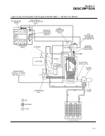
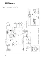
Страница 19: ...Section 2 DESCRIPTION 13 Figure 2 4A Control System with Piping and Instrumentation 185H 210H Models...
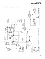
Страница 20: ...Section 2 DESCRIPTION 14 Figure 2 4B Control System with Piping and Instrumentation 260 Models...
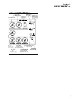
Страница 23: ...Section 2 DESCRIPTION 17 Figure 2 6 Instrument Panel Group...
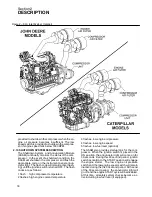
Страница 24: ...Section 2 DESCRIPTION 18 Figure 2 7 Electrical System JOHN DEERE 02250144 446R05...
Страница 25: ...Section 2 DESCRIPTION 19 Figure 2 7A Electrical System CATERPILLAR P02250144 395R04...
Страница 26: ...20 NOTES...
Страница 30: ...24 NOTES...
Страница 36: ...Section 5 MAINTENANCE 30 Figure 5 4 Control System Adjustment 185H 210 MODELS 260 MODELS...
Страница 42: ...36 NOTES...
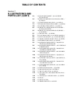
Страница 49: ...Section 7 ILLUSTRATIONS AND PARTS LIST 43 NOTES...
Страница 50: ...Section 7 ILLUSTRATIONS AND PARTS LIST 44 7 3A ENGINE COMPRESSOR PARTS 185H 210H CATERPILLAR 02250149 637R02...
Страница 52: ...Section 7 ILLUSTRATIONS AND PARTS LIST 46 7 3A ENGINE COMPRESSOR PARTS 185H 210H CATERPILLAR 02250149 637R02...
Страница 54: ...Section 7 ILLUSTRATIONS AND PARTS LIST 48 7 3B ENGINE COMPRESSOR PARTS 260 CATERPILLAR 02250149 631R02...
Страница 56: ...Section 7 ILLUSTRATIONS AND PARTS LIST 50 7 3B ENGINE COMPRESSOR PARTS 260 CATERPILLAR 02250149 631R02...
Страница 58: ...Section 7 ILLUSTRATIONS AND PARTS LIST 52 7 3C ENGINE COMPRESSOR PARTS 185H 210H JOHN DEERE 02250149 639R02...
Страница 60: ...Section 7 ILLUSTRATIONS AND PARTS LIST 54 7 3C ENGINE COMPRESSOR PARTS 185H 210H JOHN DEERE 02250149 639R02...
Страница 62: ...Section 7 ILLUSTRATIONS AND PARTS LIST 56 7 3D ENGINE COMPRESSOR PARTS 260 JOHN DEERE 02250149 634R02...
Страница 64: ...Section 7 ILLUSTRATIONS AND PARTS LIST 58 7 3D ENGINE COMPRESSOR PARTS 260 JOHN DEERE continued 02250149 634R02...
Страница 66: ...Section 7 ILLUSTRATIONS AND PARTS LIST 60 7 4A AIR INLET AND EXHAUST ALL CATERPILLAR MODELS 02250149 632R00...
Страница 68: ...Section 7 ILLUSTRATIONS AND PARTS LIST 62 7 4B AIR INLET AND EXHAUST ALL JOHN DEERE MODELS 02250149 636R00...
Страница 76: ...Section 7 ILLUSTRATIONS AND PARTS LIST 70 7 7A FRAME RUNNING GEAR PARTS ALL MODELS 02250155 667R00...
Страница 78: ...Section 7 ILLUSTRATIONS AND PARTS LIST 72 7 7A FRAME RUNNING GEAR PARTS ALL MODELS 02250155 667R00...
Страница 80: ...Section 7 ILLUSTRATIONS AND PARTS LIST 74 7 7B FRAME LESS RUNNING GEAR PARTS ALL MODELS 02250151 314R00...
Страница 82: ...Section 7 ILLUSTRATIONS AND PARTS LIST 76 7 7B FRAME LESS RUNNING GEAR PARTS ALL MODELS 02250151 314R00...
Страница 84: ...Section 7 ILLUSTRATIONS AND PARTS LIST 78 7 8 DISCHARGE SYSTEM AND PARTS ALL MODELS 02250149 638R01...
Страница 86: ...Section 7 ILLUSTRATIONS AND PARTS LIST 80 7 8 DISCHARGE SYSTEM AND PARTS ALL MODELS 02250149 638R01...
Страница 90: ...Section 7 ILLUSTRATIONS AND PARTS LIST 84 7 10 ELECTRICAL PARTS ALL MODELS 02250148 897R00...
Страница 92: ...Section 7 ILLUSTRATIONS AND PARTS LIST 86 7 11A FUEL TANK AND PARTS ALL CATERPILLAR MODELS 02250148 847R01...
Страница 94: ...Section 7 ILLUSTRATIONS AND PARTS LIST 88 7 11B FUEL TANK AND PARTS ALL JOHN DEERE MODELS 02250149 635R01...
Страница 96: ...Section 7 ILLUSTRATIONS AND PARTS LIST 90 7 12 CANOPY ACOUSTICAL PANELS PARTS ALL MODELS 02250151 313R00...
Страница 98: ...Section 7 ILLUSTRATIONS AND PARTS LIST 92 7 12 CANOPY ACOUSTICAL PANELS PARTS ALL MODELS 02250151 313R00...
Страница 112: ...Section 7 ILLUSTRATIONS AND PARTS LIST 106 7 14F INSTRUMENT PANEL AND PARTS 260 CATERPILLAR FULL GAUGE 02250154 338R02...
Страница 116: ...Section 7 ILLUSTRATIONS AND PARTS LIST 110 7 14H INSTRUMENT PANEL AND PARTS 260 JOHN DEERE FULL GAUGE 02250154 443R02...
Страница 118: ...Section 7 ILLUSTRATIONS AND PARTS LIST 112 7 15 SINGLE HOSE REEL OPTION ALL MODELS 02250151 192R01...
Страница 120: ...Section 7 ILLUSTRATIONS AND PARTS LIST 114 7 16 DUAL HOSE REEL OPTION ALL MODELS 02250141 690R02...
Страница 122: ...Section 7 ILLUSTRATIONS AND PARTS LIST 116 7 17 ONE PINT OILER OPTION ALL MODELS 02250151 189R00...
Страница 124: ...Section 7 ILLUSTRATIONS AND PARTS LIST 118 7 18 ONE QUART OILER MOISTURE SEPARATOR OPTIONS ALL MODELS 02250151 191R00...
Страница 126: ...Section 7 ILLUSTRATIONS AND PARTS LIST 120 7 19 CANADIAN TAIL CLEARANCE LIGHTS ALL MODELS 02250150 874R00...
Страница 128: ...Section 7 ILLUSTRATIONS AND PARTS LIST 122 7 20 DECALS...
Страница 130: ...Section 7 ILLUSTRATIONS AND PARTS LIST 124 7 20 DECALS...
Страница 132: ...Section 7 ILLUSTRATIONS AND PARTS LIST 126 7 20 DECALS...
Страница 134: ...Section 7 ILLUSTRATIONS AND PARTS LIST 128 7 20 DECALS...
Страница 136: ...Section 7 ILLUSTRATIONS AND PARTS LIST 130 7 20 DECALS...
Страница 138: ...Section 7 ILLUSTRATIONS AND PARTS LIST 132 7 21 DECAL LOCATIONS 02250149 633R01...
Страница 140: ...Section 7 ILLUSTRATIONS AND PARTS LIST 134 7 22 DRAWBAR INSTALLATION ALL MODELS 02250141 874R00...
Страница 142: ......
Страница 143: ......


