


Section 2
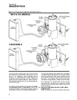
DESCRIPTION
12
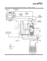
Figure 2---3 Compressor Discharge System
nents when compressor is running or pressurized.
Stop compressor and relieve all internal pressure be-
fore doing so.
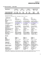
2.6 CAPACITY CONTROL SYSTEM, FUNCTIONAL
DESCRIPTION
Refer to Figures
or
. The purpose
of the control system is to regulate the amount of air
intake in accordance with the amount of com-
pressed air being used.
The control system con-
sists of a pressure regulating valve(s), air inlet
valve, system blowdown valve, and tubing con-
necting the various components to the compres-
sor and engine governor
. The functional descrip-
tions of the control system are given in four distinct
phases of operation. It applies to any control system
with the exception of those with stated pressures
which are dependent on pressure requirements.
The pressures stated will be in accordance with a
compressor having an operating pressure range of
100 to 110 psig (6.9 to 7.6bar).
START -- 0 TO 40 PSIG (0 TO 2.8 BAR)
COLD WEATHER
To minimize problems in cold weather, starting aids,
engine coolant heaters and dry---side receiver relief
valves should be used. Refer to the engine opera-
tors manual for additional information.
Содержание 185H
Страница 6: ......
Страница 14: ...8 NOTES...
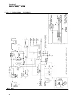
Страница 19: ...Section 2 DESCRIPTION 13 Figure 2 4A Control System with Piping and Instrumentation 185H 210H Models...
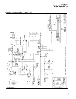
Страница 20: ...Section 2 DESCRIPTION 14 Figure 2 4B Control System with Piping and Instrumentation 260 Models...
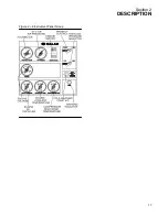
Страница 23: ...Section 2 DESCRIPTION 17 Figure 2 6 Instrument Panel Group...
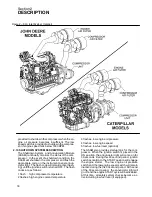
Страница 24: ...Section 2 DESCRIPTION 18 Figure 2 7 Electrical System JOHN DEERE 02250144 446R05...
Страница 25: ...Section 2 DESCRIPTION 19 Figure 2 7A Electrical System CATERPILLAR P02250144 395R04...
Страница 26: ...20 NOTES...
Страница 30: ...24 NOTES...
Страница 36: ...Section 5 MAINTENANCE 30 Figure 5 4 Control System Adjustment 185H 210 MODELS 260 MODELS...
Страница 42: ...36 NOTES...
Страница 49: ...Section 7 ILLUSTRATIONS AND PARTS LIST 43 NOTES...
Страница 50: ...Section 7 ILLUSTRATIONS AND PARTS LIST 44 7 3A ENGINE COMPRESSOR PARTS 185H 210H CATERPILLAR 02250149 637R02...
Страница 52: ...Section 7 ILLUSTRATIONS AND PARTS LIST 46 7 3A ENGINE COMPRESSOR PARTS 185H 210H CATERPILLAR 02250149 637R02...
Страница 54: ...Section 7 ILLUSTRATIONS AND PARTS LIST 48 7 3B ENGINE COMPRESSOR PARTS 260 CATERPILLAR 02250149 631R02...
Страница 56: ...Section 7 ILLUSTRATIONS AND PARTS LIST 50 7 3B ENGINE COMPRESSOR PARTS 260 CATERPILLAR 02250149 631R02...
Страница 58: ...Section 7 ILLUSTRATIONS AND PARTS LIST 52 7 3C ENGINE COMPRESSOR PARTS 185H 210H JOHN DEERE 02250149 639R02...
Страница 60: ...Section 7 ILLUSTRATIONS AND PARTS LIST 54 7 3C ENGINE COMPRESSOR PARTS 185H 210H JOHN DEERE 02250149 639R02...
Страница 62: ...Section 7 ILLUSTRATIONS AND PARTS LIST 56 7 3D ENGINE COMPRESSOR PARTS 260 JOHN DEERE 02250149 634R02...
Страница 64: ...Section 7 ILLUSTRATIONS AND PARTS LIST 58 7 3D ENGINE COMPRESSOR PARTS 260 JOHN DEERE continued 02250149 634R02...
Страница 66: ...Section 7 ILLUSTRATIONS AND PARTS LIST 60 7 4A AIR INLET AND EXHAUST ALL CATERPILLAR MODELS 02250149 632R00...
Страница 68: ...Section 7 ILLUSTRATIONS AND PARTS LIST 62 7 4B AIR INLET AND EXHAUST ALL JOHN DEERE MODELS 02250149 636R00...
Страница 76: ...Section 7 ILLUSTRATIONS AND PARTS LIST 70 7 7A FRAME RUNNING GEAR PARTS ALL MODELS 02250155 667R00...
Страница 78: ...Section 7 ILLUSTRATIONS AND PARTS LIST 72 7 7A FRAME RUNNING GEAR PARTS ALL MODELS 02250155 667R00...
Страница 80: ...Section 7 ILLUSTRATIONS AND PARTS LIST 74 7 7B FRAME LESS RUNNING GEAR PARTS ALL MODELS 02250151 314R00...
Страница 82: ...Section 7 ILLUSTRATIONS AND PARTS LIST 76 7 7B FRAME LESS RUNNING GEAR PARTS ALL MODELS 02250151 314R00...
Страница 84: ...Section 7 ILLUSTRATIONS AND PARTS LIST 78 7 8 DISCHARGE SYSTEM AND PARTS ALL MODELS 02250149 638R01...
Страница 86: ...Section 7 ILLUSTRATIONS AND PARTS LIST 80 7 8 DISCHARGE SYSTEM AND PARTS ALL MODELS 02250149 638R01...
Страница 90: ...Section 7 ILLUSTRATIONS AND PARTS LIST 84 7 10 ELECTRICAL PARTS ALL MODELS 02250148 897R00...
Страница 92: ...Section 7 ILLUSTRATIONS AND PARTS LIST 86 7 11A FUEL TANK AND PARTS ALL CATERPILLAR MODELS 02250148 847R01...
Страница 94: ...Section 7 ILLUSTRATIONS AND PARTS LIST 88 7 11B FUEL TANK AND PARTS ALL JOHN DEERE MODELS 02250149 635R01...
Страница 96: ...Section 7 ILLUSTRATIONS AND PARTS LIST 90 7 12 CANOPY ACOUSTICAL PANELS PARTS ALL MODELS 02250151 313R00...
Страница 98: ...Section 7 ILLUSTRATIONS AND PARTS LIST 92 7 12 CANOPY ACOUSTICAL PANELS PARTS ALL MODELS 02250151 313R00...
Страница 112: ...Section 7 ILLUSTRATIONS AND PARTS LIST 106 7 14F INSTRUMENT PANEL AND PARTS 260 CATERPILLAR FULL GAUGE 02250154 338R02...
Страница 116: ...Section 7 ILLUSTRATIONS AND PARTS LIST 110 7 14H INSTRUMENT PANEL AND PARTS 260 JOHN DEERE FULL GAUGE 02250154 443R02...
Страница 118: ...Section 7 ILLUSTRATIONS AND PARTS LIST 112 7 15 SINGLE HOSE REEL OPTION ALL MODELS 02250151 192R01...
Страница 120: ...Section 7 ILLUSTRATIONS AND PARTS LIST 114 7 16 DUAL HOSE REEL OPTION ALL MODELS 02250141 690R02...
Страница 122: ...Section 7 ILLUSTRATIONS AND PARTS LIST 116 7 17 ONE PINT OILER OPTION ALL MODELS 02250151 189R00...
Страница 124: ...Section 7 ILLUSTRATIONS AND PARTS LIST 118 7 18 ONE QUART OILER MOISTURE SEPARATOR OPTIONS ALL MODELS 02250151 191R00...
Страница 126: ...Section 7 ILLUSTRATIONS AND PARTS LIST 120 7 19 CANADIAN TAIL CLEARANCE LIGHTS ALL MODELS 02250150 874R00...
Страница 128: ...Section 7 ILLUSTRATIONS AND PARTS LIST 122 7 20 DECALS...
Страница 130: ...Section 7 ILLUSTRATIONS AND PARTS LIST 124 7 20 DECALS...
Страница 132: ...Section 7 ILLUSTRATIONS AND PARTS LIST 126 7 20 DECALS...
Страница 134: ...Section 7 ILLUSTRATIONS AND PARTS LIST 128 7 20 DECALS...
Страница 136: ...Section 7 ILLUSTRATIONS AND PARTS LIST 130 7 20 DECALS...
Страница 138: ...Section 7 ILLUSTRATIONS AND PARTS LIST 132 7 21 DECAL LOCATIONS 02250149 633R01...
Страница 140: ...Section 7 ILLUSTRATIONS AND PARTS LIST 134 7 22 DRAWBAR INSTALLATION ALL MODELS 02250141 874R00...
Страница 142: ......
Страница 143: ......


