Section 2
DESCRIPTION
8
2.1 INTRODUCTION
The Sullair 175,185 or 185H CFM Portable Air Com-
pressors offer superior performance and reliability
along with a minimal amount of maintenance re-
quirements.
The compressor is equipped with a Sullair rotary
screw compressor unit. Compared to other com-
pressors, the Sullair is unique in mechanical reliabil-
ity and compressor durability. No inspection is re-
quired of the working parts within the compressor
unit.
As you continue reading this manual and come to
learn how the compressor operates and is cared for,
you will see how surprisingly easy it is to keep a Sull-
air compressor in top operating condition.
Read Section 5 (Maintenance) and learn how to
keep your compressor in top operating condition.
Should any problem or question arise which cannot
be answered in this text, contact your nearest Sullair
representative or the Sullair Corporation Service
Department.
2.2 DESCRIPTION OF COMPONENTS
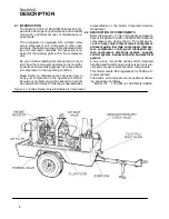
Refer to Figures 2---1. The components and assem-
blies of the Sullair 175,185 or 185H CFM Portable Air
compressors are clearly shown. The package in-
cludes a
heavy duty rotary screw air compressor,
a diesel engine, fuel tank, compressor inlet sys-
tem, compressor cooling and lubrication sys-
tem, compressor discharge system, capacity
control system, instrument panel and electrical
system.
A one---piece, low profile canopy offers improved
handling and mobility. Large side service doors pro-
vide easy access to all serviceable components.
This model meets EPA regulations for 76dbA at 7
meters (23 feet).
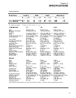
The Sullair air compressors are capable of deliver-
ing capacities as follows:
Model 175
175 CFM @ 100 PSIG (6.9 BAR)
Figure 2---1 Sullair Rotary Screw Portable Air Compressor
Содержание 175
Страница 6: ...NOTES ...
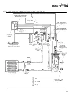
Страница 18: ...Section 2 DESCRIPTION 12 Figure 2 4A Control System with Piping and Instrumentation 175 185 Models ...
Страница 19: ...Section 2 DESCRIPTION 13 Figure 2 4B Control System with Piping and Instrumentation 185H Models ...
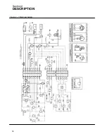
Страница 22: ...Section 2 DESCRIPTION 16 Figure 2 7 Electrical System ...
Страница 40: ...Section 7 ILLUSTRATIONS AND PARTS LIST 34 7 3A ENGINE COMPRESSOR AND PARTS SPEED CYLINDER ASSEMBLY 175 MODELS ...
Страница 42: ...Section 7 ILLUSTRATIONS AND PARTS LIST 36 7 3A ENGINE COMPRESSOR AND PARTS SPEED CYLINDER ASSEMBLY 175 MODELS ...
Страница 44: ...Section 7 ILLUSTRATIONS AND PARTS LIST 38 7 3B ENGINE COMPRESSOR AND PARTS SPEED CYLINDER ASSEMBLY 185 MODELS ...
Страница 46: ...Section 7 ILLUSTRATIONS AND PARTS LIST 40 7 3B ENGINE COMPRESSOR AND PARTS SPEED CYLINDER ASSEMBLY 185 MODELS ...
Страница 48: ...Section 7 ILLUSTRATIONS AND PARTS LIST 42 7 3C ENGINE COMPRESSOR AND PARTS SPEED CYLINDER ASSEMBLY 185H MODELS ...
Страница 50: ...Section 7 ILLUSTRATIONS AND PARTS LIST 44 7 3C ENGINE COMPRESSOR AND PARTS SPEED CYLINDER ASSEMBLY 185H MODELS ...
Страница 52: ...Section 7 ILLUSTRATIONS AND PARTS LIST 46 7 4A RADIATOR COMPRESSOR FLUID SYSTEM 175 MODELS ...
Страница 54: ...Section 7 ILLUSTRATIONS AND PARTS LIST 48 7 4A RADIATOR COMPRESSOR FLUID SYSTEM 175 MODELS ...
Страница 56: ...Section 7 ILLUSTRATIONS AND PARTS LIST 50 7 4B RADIATOR COMPRESSOR FLUID SYSTEM 185 185H MODELS ...
Страница 58: ...Section 7 ILLUSTRATIONS AND PARTS LIST 52 7 4B RADIATOR COMPRESSOR FLUID SYSTEM 185 185H MODELS ...
Страница 60: ...Section 7 ILLUSTRATIONS AND PARTS LIST 54 7 5 FRAME AXLE PARTS AXLE ASSEMBLY Exploded View ALL MODELS ...
Страница 62: ...Section 7 ILLUSTRATIONS AND PARTS LIST 56 7 5 FRAME AXLE PARTS AXLE ASSEMBLY Exploded View ALL MODELS ...
Страница 66: ...Section 7 ILLUSTRATIONS AND PARTS LIST 60 7 6A RECEIVER PNEUMATIC CONTROL SERVICE VALVE 175 185 MODELS ...
Страница 68: ...Section 7 ILLUSTRATIONS AND PARTS LIST 62 7 6B RECEIVER PNEUMATIC CONTROL SERVICE VALVE ASSEMBLY 185H MODELS ...
Страница 70: ...Section 7 ILLUSTRATIONS AND PARTS LIST 64 7 6B RECEIVER PNEUMATIC CONTROL SERVICE VALVE ASSEMBLY 185H MODELS ...
Страница 76: ...Section 7 ILLUSTRATIONS AND PARTS LIST 70 7 9A ELECTRICAL PARTS ENGINE OIL PRESSURE SWITCH ASSEMBLY 175 MODELS ...
Страница 78: ...Section 7 ILLUSTRATIONS AND PARTS LIST 72 7 9B ELECTRICAL PARTS 185 185H MODELS ...
Страница 80: ...Section 7 ILLUSTRATIONS AND PARTS LIST 74 7 10 INSTRUMENT PANEL PARTS ALL MODELS ...
Страница 82: ...Section 7 ILLUSTRATIONS AND PARTS LIST 76 7 11A AIR INLET AND EXHAUST 175 MODELS ...
Страница 84: ...Section 7 ILLUSTRATIONS AND PARTS LIST 78 7 11B AIR INLET AND EXHAUST 185 185H MODELS ...
Страница 86: ...Section 7 ILLUSTRATIONS AND PARTS LIST 80 7 12 FUEL TANK CONNECTIONS ALL MODELS ...
Страница 88: ...Section 7 ILLUSTRATIONS AND PARTS LIST 82 7 13A CANOPY PARTS 175 MODELS ...
Страница 90: ...Section 7 ILLUSTRATIONS AND PARTS LIST 84 7 13B CANOPY PARTS 185 185H MODELS ...
Страница 92: ...Section 7 ILLUSTRATIONS AND PARTS LIST 86 7 14 DECALS ...
Страница 94: ...Section 7 ILLUSTRATIONS AND PARTS LIST 88 7 14 DECALS ...
Страница 96: ...Section 7 ILLUSTRATIONS AND PARTS LIST 90 7 14 DECALS ...
Страница 99: ......


