background image

Section 2

DESCRIPTION

12

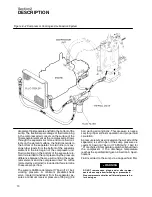
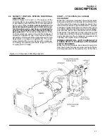
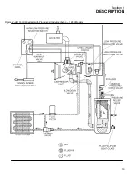
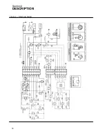
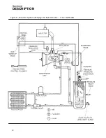
Figure 2---4A Control System with Piping and Instrumentation --- 175 & 185 Models

Содержание 175

Страница 1: ...PORTABLE OPERATOR S MANUAL AND AIR COMPRESSOR PARTS LIST 175 185H JOHN DEERE Part Number 02250059 158 Sullair Corporation KEEP FOR FUTURE REFERENCE ...

Страница 2: ...ers in Michigan City Indiana Instruction includes discussion of the function and installation of Sullair service parts troubleshooting of the most common problems and actual equipment operation The seminars are recommended for rental house and Contractor Maintenance and service personnel For detailed course outlines schedule and cost information contact Sullair Corporate Training Department 1 800 ...

Страница 3: ... SULLAIR COMPRESSOR UNIT FUNCTIONAL DESCRIPTION 9 2 4 COMPRESSOR COOLING AND LUBRICATION SYSTEM FUNCTIONAL DESCRIPTION 9 2 5 COMPRESSOR DISCHARGE SYSTEM FUNCTIONAL DESCRIPTION 11 2 6 CONTROL SYSTEM FUNCTIONAL DESCRIPTION 14 2 7 AIR INLET SYSTEM FUNCTIONAL DESCRIPTION 14 2 8 INSTRUMENT PANEL GROUP FUNCTIONAL DESCRIPTION 15 2 9 ELECTRICAL SYSTEM FUNCTIONAL DESCRIPTION Section 3 SPECIFICATIONS 17 TAB...

Страница 4: ...URE FOR ORDERING PARTS 34 7 2 RECOMMENDED SPARE PARTS LIST 35 7 3A ENGINE COMPRESSOR AND PARTS AND SPEED CYLINDER ASSEMBLY 175 MODELS 39 7 3B ENGINE COMPRESSOR AND PARTS AND SPEED CYLINDER ASSEMBLY 185 MODELS 43 7 3C ENGINE COMPRESSOR AND PARTS AND SPEED CYLINDER ASSEMBLY 185H MODELS 47 7 4A RADIATOR AND COMPRESSOR FLUID SYSTEM 175 MODELS 51 7 4B RADIATOR AND COMPRESSOR FLUID SYSTEM 185 185H MODEL...

Страница 5: ...5H MODELS 75 7 10 INSTRUMENT PANEL AND PARTS ALL MODELS 77 7 11A AIR INLET AND EXHAUST 175 MODELS 79 7 11B AIR INLET AND EXHAUST 185 185H MODELS 81 7 12 FUEL TANK AND CONNECTIONS ALL MODELS 83 7 13A CANOPY AND PARTS 175 MODEL 85 7 13B CANOPY AND PARTS 185 185H MODELS 87 7 14 DECALS ...

Страница 6: ...NOTES ...

Страница 7: ...ent dented or otherwise deformed or degraded and iii loose nuts bolts or other fasteners Should any such condition be present DO NOT TOW until the problem is corrected 2 Back the tow vehicle to the compressor and position it in preparation for coupling the com pressor 3 If the compressor is provided with a drawbar latched in the vertical upright position carefully unlatch drawbar and lower it to e...

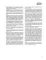
Страница 8: ...ile towing this equipment including those specifying minimum speed 2 DO NOT exceed the towing speeds listed be low under ideal conditions Reduce your speed according to posted speed limits weather traf fic road or terrain conditions a Two axle four wheel steerable models 15MPH 24KMPH b All other models 55 MPH 88KMPH 3 Remember that the portable air compressor may approach or exceed the weight of t...

Страница 9: ...SSURE RELEASE A Open the pressure relief valve at least weekly to make sure it is not blocked closed obstructed or otherwise disabled B Install an appropriate flow limiting valve be tween the compressor service air outlet and the shutoff throttle valve when an air hose exceed ing 1 2 13mm inside diameter is to be connected to shut off throttle valve to reduce pressure in case of hose failure per O...

Страница 10: ...he material DO NOT use flammable solvents for cleaning purposes E Disconnect the grounded negative battery connection prior to attempting any repairs or clean ing inside the enclosure Tag the battery connec tions so others will not unexpectedly reconnect it F Keep electrical wiring including the battery ter minals and other terminals in good condition Re place any wiring that has cracked cut abrad...

Страница 11: ...essary start the engine and check adjustment If adjustment is in correct shut engine off readjust then restart the engine to recheck adjustment I Keep hands feet floors controls and walking surfaces clean and free of fluid water antifreeze or other liquids to minimize possibility of slips and falls 1 6 HOT SURFACES SHARP EDGES AND SHARP CORNERS A Avoid bodily contact with hot fluid hot coolant hot...

Страница 12: ...l regulations that may apply B Inspect lifting bail and points of attachment for cracked welds and for cracked bent corroded or otherwise degraded members and for loose bolts or nuts prior to lifting C Make sure entire lifting rigging and supporting structure has been inspected is in good condition and has a rated capacity of at least the net weight of the compressor plus an additional 10 allowanc...

Страница 13: ...sors and if the starting vehicle is provided with two 2 12V bat teries connected in series connect the jumper ca ble to the positive POS terminal of the un grounded battery P Connect the other end of the same jumper cable to the positive POS terminal of the starter mo tor battery in the compressor or when jump start ing 24V compressor to the positive POS ter minal of the ungrounded battery in the ...

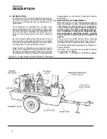
Страница 14: ...uld any problem or question arise which cannot be answered in this text contact your nearest Sullair representative or the Sullair Corporation Service Department 2 2 DESCRIPTION OF COMPONENTS Refer to Figures 2 1 The components and assem blies of the Sullair 175 185 or 185H CFM Portable Air compressors are clearly shown The package in cludes a heavy duty rotary screw air compressor a diesel engine...

Страница 15: ...maintain the proper operating temperature of the compressor In addition to the fluid cooler and interconnecting piping the sys tem consists also of three other components a fluid filter thermal valve and a fan which perform the following functions S The fluid filter filters the fluid S The thermal valve functions as a temperatureregu lator directing fluid either to the cooler or to the com pressor...

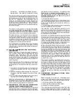
Страница 16: ...r inlet An orifice protected by a strainer is included in this returnline to assure proper flow The sump is ASME code rated at 175 psig 12 1 bar working pressure A minimum pressure check valve located downstream from the separator as sures a minimum receiver pressure of 55 psig 3 8 bar during all conditions This pressure is neces sary for proper air fluid separation and proper fluid circulation A ...

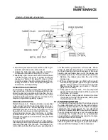
Страница 17: ...g pressure range of 100 to 110 psig 6 9 to 7 6bar START 0 TO 40 PSIG 0 to 2 8 BAR COLD START When the compressor is started the sump pressure will quickly rise from 0 to 40 psig 0 to 2 8 bar Dur ing this period the pressure regulator valve is inac tive At this pressure range the idle warm up valve maintains a closed inlet valve for engine idle opera tion After sufficient machine warm up is achieve...

Страница 18: ...Section 2 DESCRIPTION 12 Figure 2 4A Control System with Piping and Instrumentation 175 185 Models ...

Страница 19: ...Section 2 DESCRIPTION 13 Figure 2 4B Control System with Piping and Instrumentation 185H Models ...

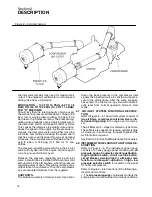
Страница 20: ...valve is open This allows variance of air output to match air demand The orifice also bleeds any accumulated moisture from the regulator SHUTDOWN The blowdown valve is normally closed Upon shut down the back pressure in the compressor inlet signals the blowdown valve to vent the sump pres sure to the atmosphere After the sump pressure has vented the idle warm up valve will automati cally reset fro...

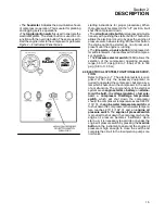
Страница 21: ... the selection of the compressor operating pressure range 55 to 110 psig 3 8 to 7 6 bar or 55 to 160 psig 3 8 to 11 0 bar 2 9 ELECTRICAL SYSTEM FUNCTIONAL DESCRIP TION Refer to Figure 2 7 The electrical system is com prised of not only the necessary equipment re quired to operated the compressor but also a sys tem which shuts down the compressor in the event of a malfunction The components of the ...

Страница 22: ...Section 2 DESCRIPTION 16 Figure 2 7 Electrical System ...

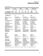
Страница 23: ...ssor Discharge Shutdown 240_F Shutdown 240_F Shutdown 240_F Temp 116_C 116_C 116_C Service Valves 2 3 4 2 3 4 2 3 4 Maximum Towing Speed 55 mph 88 kmph 55 mph 88 kmph 55 mph 88 kmph Axle Rating 3500 lbs 1588 kg 3500 lbs 1588 kg 3500 lbs 1588 kg Rated Pressure 100 psig 7 bar 100 psig 7 bar 150 psig 10 bar Sound Level 76 dBA at 7 meters 76 dBA at 7 meters 76 dBA at 7 meters ENGINE Type Diesel Diesel...

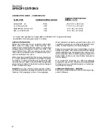
Страница 24: ...ity conditions condensed moisture may emulsify with the oil forming a milky color SAE 10W is especially prone to this condition The fluid should be changed if this condition develops DO NOT mix types of fluids Combinations of differ ent fluids may lead to operational problems such as foaming filter plugging orifice or line plugging When ambient conditions exceed those noted or if conditions warran...

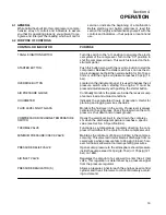
Страница 25: ...rs the pressure inside the receiver sump at various load and unload conditions HOURMETER Indicates the accumulated hours of operation Useful for planning and logging service schedules FLUID LEVEL SIGHT GLASS Monitors the fluid level in the sump Proper level is always centered in the sight glass Check the level when the com pressor is shut down and on level ground COMPRESSOR DISCHARGE TEMPERATURE O...

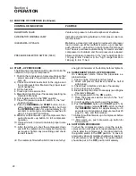
Страница 26: ...ig 1 4 bar and then release 9 Allow for sufficient warm up of compressor then push idle warm up button for full compressor operation 10 Close all doors in order to maintain proper noise control 11 After the initial run shut the compressor down and refill the radiator and compressor fluid sump as required Tighten any loose fittings and check fan belt tension I The radiator is filled with a 50 50 mi...

Страница 27: ...d 5 3 MAINTENANCE AFTER INITIAL 50 HOURS OF OPERATION After the initial 50 hours of operation a few mainte nance requirements are needed to rid the system of any foreign materials Perform the following mainte nance operations to prevent unnecessary prob lems 1 Clean the return line orifice and strainer 2 Change compressor fluid filter 3 Check Engine Operator s Manual for required service 5 4 MAINT...

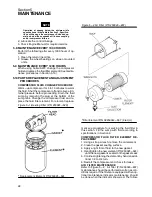
Страница 28: ...uid sump by removing the plug at the bottom of the sump tank Change the compressor fluid and re place the fluid filter element For element replace Figure 5 1 Bearing Filter P N 250025 520 Replacement Element P N 250025 524 Figure 5 2 Air Filter P N 250040 807 Filter Element P N 02250044 537 2 req d ment see procedure for servicing the fluid filter in this section Fill the sump with fluid according...

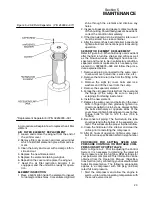
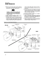
Страница 29: ...ined below 1 Remove all piping connected to the sump cover to allow removal return line service line etc 2 Remove the fluid return line from the fitting in the cover 3 Remove the eight 8 cover bolts and lock washers and lift the cover from the sump 4 Remove the separator element 5 Scrape the old gasket material from the cover and the flange on the sump Be sure to keep all scrapings from falling in...

Страница 30: ...ed to its specified setting by adjusting the high idle threaded rodlo cated on the engine speed control To raise or lower the speed lengthen or shorten the rod re spectively 5 Open the service valve to 100 psig 6 9 bar rated full load pressure and recheck top engine speed and control response Close the service valve and allow the compressor to cycle and re check low engine speed idle The following...

Страница 31: ...re the bearings can be periodically lubricated without removing the hubs from the axle This feature con sists of axle spindles that have been specially drilled and fitted with a grease zerk in their ends When grease is pumped into the zerk it is channeled to the inner bearing and then flows back to the outer bearing and eventually back out of the grease cap hold see Figure 5 5 The procedure is as ...

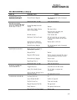
Страница 32: ...UTS DOWN WITH AIR DEMAND PRESENT No Fuel Check fuel level and add fuel if necessary Compressor Discharge Temperature Switch Is Open Cooling air flow is insufficient clean cooler and check for proper ventilation Low fluid sump level add fluid Clogged compressor fluid filter change element The temperature regulating section of the fluid control center is not functioning properly change the thermosta...

Страница 33: ...Too Low Of Pressure Defective Pressure Regulator Check diaphragm and replace if necessary kit available INSUFFICIENT AIR DELIVERY Engage Idle Warm up Valve For Full Compressor Operation Plugged Air Filter Replace Plugged Air Fluid Separator Replace separator element and also change compressor fluid and fluid filter at this time Defective Pressure Regulator Adjust or repair Engine Speed Too Low Rea...

Страница 34: ... CAUSE REMEDY ENGINE OVERHEATING Loose Or Broken Fan Belt Tighten or change belt Dirty Radiator Core Clean thoroughly Low Fluid Level Refill Faulty Water Pump Change pump Plugged Radiator Clean and flush thoroughly Defective Engine Thermostat Replace engine thermostat ...

Страница 35: ...ved or ren dered inoperative by any person Among those acts included in the prohibition against tampering are the acts listed below 1 Removal or rendering inoperative any of the fol lowing a Engine exhaust system or parts thereof b Compressor air intake system or part thereof c Enclosure of part thereof 2 Removal of any of the following a Vibration isolators b Control silencer c Floor panel d Fan ...

Страница 36: ...ssor with defective air inlet system Remove and replace defective parts by ordering with part numbers indicated in the Parts List Maintenance Performed By Location Date Maintenance Performed By Location Date DDDDDDDDDDDDDDDDD 3 ANNUAL ENGINE VIBRATION MOUNT INSPECTION At least annually inspect engine vibration mounts for security of attachment and to make sure the resilient parts are intact DO NOT...

Страница 37: ...ted in Parts List Maintenance Performed By Location Date Maintenance Performed By Location Date DDDDDDDDDDDDDDDDD 5 ANNUAL ACOUSTICAL MATERIALS INSPECTION At least annually inspect all acoustical materials if any for security of attachment Make sure that there is not any material missing or damaged refer to Parts List Clean or replace if necessary DO NOT operate com pressor with defective acoustic...

Страница 38: ...lly operate compressor and inspect to make sure all systems are operating properly and that engine runs at rated speed and pressure DO NOT operate malfunctioning or improperly adjusted compressor Repair or adjust per instructions in Operator s Manual as required Maintenance Performed By Location Date Maintenance Performed By Location Date DDDDDDDDDDDDDDDDD ...

Страница 39: ... FAX 219 874 1805 Service 7 2 RECOMMENDED SPARE PARTS LIST Description Kit Number Quantity element for air filter assy 250040 807 02250044 537 2 element for main compressor fluid filter 250025 520 250025 524 1 element for air fluid separator 02250078 031 1 repair kit for blowdown valve 250025 655 250031 771 1 repair kit for thermal valve 409193 250017 340 1 repair kit for pressure regulator valve ...

Страница 40: ...Section 7 ILLUSTRATIONS AND PARTS LIST 34 7 3A ENGINE COMPRESSOR AND PARTS SPEED CYLINDER ASSEMBLY 175 MODELS ...

Страница 41: ...ead 1 4 20 x 1 1 4 828404 125 2 20 sub assembly adapter oil pan drain 221187 1 21 plug oil drain jd 242529 1 22 sub assembly eng compr 175 dpq 02250073 388 1 23 engine 3 179d jd 250021 375 1 24 adapter SAE 4 02250071 119 1 25 compressor part dxx102147b304s43ac I 251274 001 1 26 valve air inlet 2 1 2 85 125q II 250017 279 1 27 tube steel 1 4 fuel return 250011 577 1 28 o ring neoprene 3 1 2 x 1 8 8...

Страница 42: ...Section 7 ILLUSTRATIONS AND PARTS LIST 36 7 3A ENGINE COMPRESSOR AND PARTS SPEED CYLINDER ASSEMBLY 175 MODELS ...

Страница 43: ...8 11 x 1 1 2 828610 150 4 46 nipple pipe 1 1 2 x 6 0 sc 40 822124 060 1 47 capscrew ferry hd 5 16 x 2 1 4 828405 225 4 48 nipple pipe 1 1 2 x cl sc 80 822224 000 1 49 nipple pipe 3 4 x cl sc 80 822212 000 1 50 washer lock reg 5 8 837510 156 4 51 elbow pipe 3 4 801515 030 1 52 washer lock reg 5 16 837505 078 4 53 capscrew hex gr5 3 8 16 x 2 1 4 828606 225 2 54 washer lock reg 3 8 837506 094 21 55 c...

Страница 44: ...Section 7 ILLUSTRATIONS AND PARTS LIST 38 7 3B ENGINE COMPRESSOR AND PARTS SPEED CYLINDER ASSEMBLY 185 MODELS ...

Страница 45: ...1 4 20 x 1 1 4 828404 125 2 20 sub assembly adapter oil pan drain 221187 1 21 plug oil drain jd 242529 1 22 sub assembly eng compr 185 2w 250040 043 1 23 engine dsl jd 4 039 185 dpq 250026 853 1 24 adapter SAE 4 02250071 119 1 25 compressor part dxx102147b352s43ac I 251270 001 1 26 valve air inlet 2 1 2 85 125q II 250017 279 1 27 tube steel 1 4 fuel return 250011 577 1 28 o ring neoprene 3 1 2 x 1...

Страница 46: ...Section 7 ILLUSTRATIONS AND PARTS LIST 40 7 3B ENGINE COMPRESSOR AND PARTS SPEED CYLINDER ASSEMBLY 185 MODELS ...

Страница 47: ... 1 2 801515 060 1 45 capscrew hex gr5 5 8 11 x 1 1 2 828610 150 4 46 nipple pipe 1 1 2 x 6 0 sc 40 822124 060 1 47 capscrew ferry hd 5 16 x 2 1 4 828405 225 4 48 nipple pipe 1 1 2 x cl sc 80 822224 000 1 49 nipple pipe 3 4 x cl sc 80 822212 000 1 50 washer lock reg 5 8 837510 156 4 51 elbow pipe 3 4 801515 030 1 52 washer lock reg 5 16 837505 078 4 53 capscrew ferry hd 3 8 x 1 1 4 828406 125 19 54...

Страница 48: ...Section 7 ILLUSTRATIONS AND PARTS LIST 42 7 3C ENGINE COMPRESSOR AND PARTS SPEED CYLINDER ASSEMBLY 185H MODELS ...

Страница 49: ...1 4 20 x 1 1 4 828404 125 2 20 sub assembly adapter oil pan drain 221187 1 21 plug oil drain jd 242529 1 22 sub assembly eng compr 185h 02250071 603 1 23 engine dsl jd 4 039 185 dpq 250026 853 1 24 adapter SAE 4 02250071 119 1 25 compressor part dxx102147b352s43ac I 251270 001 1 26 valve air inlet 2 1 2 85 125q II 250017 279 1 27 tube steel 1 4 fuel return 250011 577 1 28 o ring neoprene 3 1 2 x 1...

Страница 50: ...Section 7 ILLUSTRATIONS AND PARTS LIST 44 7 3C ENGINE COMPRESSOR AND PARTS SPEED CYLINDER ASSEMBLY 185H MODELS ...

Страница 51: ...ew hex gr5 5 8 11 x 1 1 2 828610 150 4 45 nipple pipe 1 1 2 x 6 0 sc 40 822124 060 1 46 capscrew ferry hd 5 16 x 2 1 4 828405 225 4 47 nipple pipe 1 1 2 x cl sc 80 822224 000 1 48 nipple pipe 3 4 x cl sc 80 822212 000 1 49 washer lock reg 5 8 837510 156 4 50 elbow pipe 3 4 801515 030 1 51 washer lock reg 5 16 837505 078 4 52 capscrew ferry hd 3 8 x 1 1 4 828406 125 19 53 washer lock reg 3 8 837506...

Страница 52: ...Section 7 ILLUSTRATIONS AND PARTS LIST 46 7 4A RADIATOR COMPRESSOR FLUID SYSTEM 175 MODELS ...

Страница 53: ...0q 02250050 542 1 S cap radiator 040140 1 15 baffle cooler curbside 175 250q 02250050 543 1 16 cooler oil tip down 175 185 02250045 117 1 17 baffle cooler streetside 175 250q 02250050 544 1 18 hose rad up 160 jd 250009 755 1 19 hose rad low 160 jd 250009 756 1 20 sleeve 1 8 cable 575 lg 241381 2 21 grommet 1 5id x 2 1 8od x1 75 250020 358 2 22 clamp hose 1 5 16 to 2 1 4adj 040014 2 23 weatherstrip...

Страница 54: ...Section 7 ILLUSTRATIONS AND PARTS LIST 48 7 4A RADIATOR COMPRESSOR FLUID SYSTEM 175 MODELS ...

Страница 55: ... pl b r 1 4 838204 071 4 sub assembly filter thermo vlv175 185 2 II 250040 052 1 39 filter fliud 20 III 250025 520 1 40 valve thermo amot alum 3 4 409193 1 41 nipple pipe 3 4 x cl sc 80 822212 000 1 42 nipple pipe 3 4 x 2 0 sc 40 822112 020 1 43 tee straight 3 4 802415 030 1 44 connector 37f mpt 3 4 x 3 4 860112 075 2 II Consists of items 39 through 44 III For maintenance on fluid filter no 250025...

Страница 56: ...Section 7 ILLUSTRATIONS AND PARTS LIST 50 7 4B RADIATOR COMPRESSOR FLUID SYSTEM 185 185H MODELS ...

Страница 57: ...5 250q 02250050 542 1 Scap radiator 040140 1 15 baffle cooler curbside 175 250q 02250050 543 1 16 cooler oil tip down 175 185 02250045 117 1 17 baffle cooler streetside 175 250q 02250050 544 1 18 hose rad up 185 jd 250004 126 1 19 hose rad low 185 jd 250004 127 1 20 shroud fan 185 jd 250005 179 1 21 sleeve 1 8 cable 575 lg 241381 2 22 grommet 1 5id x 2 1 8od x1 75 250020 358 2 23 clamp hose 1 5 16...

Страница 58: ...Section 7 ILLUSTRATIONS AND PARTS LIST 52 7 4B RADIATOR COMPRESSOR FLUID SYSTEM 185 185H MODELS ...

Страница 59: ...her pl b r 1 4 838204 071 4 sub assembly filter thermo vlv175 185 2 II 250040 052 1 39 filter fliud 20 III 250025 520 1 40 valve thermo amot alum 3 4 409193 1 41 nipple pipe 3 4 x cl sc 80 822212 000 1 42 nipple pipe 3 4 x 2 0 sc 40 822112 020 1 43 tee straight 3 4 802415 030 1 44 connector 37f mpt 3 4 x 3 4 860112 075 2 II Consists of items 39 through 44 III For maintenance on fluid filter no 250...

Страница 60: ...Section 7 ILLUSTRATIONS AND PARTS LIST 54 7 5 FRAME AXLE PARTS AXLE ASSEMBLY Exploded View ALL MODELS ...

Страница 61: ...1 x 4 3 4 828210 475 2 16 washer lock reg 1 2 837508 125 13 17 capscrew hex gr5 7 16 14 x 1 828607 100 4 18 nut hex locking 7 16 825507 223 4 19 capscr hex gr8 1 2 13 x 1 25 828208 125 16 20 nut hex locking 5 8 825510 329 2 21 capcsr hx gr8 1 2 13 x 1 1 2 828208 150 5 22 washer pl b r 1 2 837208 112 5 23 screw ser wash 5 16x3 4 829705 075 2 24 nut hex flanged 5 16 825305 283 2 25 screw hexagon hd ...

Страница 62: ...Section 7 ILLUSTRATIONS AND PARTS LIST 56 7 5 FRAME AXLE PARTS AXLE ASSEMBLY Exploded View ALL MODELS ...

Страница 63: ...ing inner 250023 467 2 38 hub wheel 5 x 4 1 2 250023 469 2 39 stud wheel 1 2 20 250023 468 10 40 nut wheel 1 2 20 250023 470 10 41 cap grease 250040 785 2 42 plug rubber 250040 786 2 43 nut spindle 040122 2 44 washer spindle 047874 2 45 bearing outer 250023 466 2 46 plate tie 045197 2 47 nut U bolt 1 2 20 047881 8 48 spring underslung 02250051 990 2 49 washer tang 250040 784 2 PLEASE NOTE WHEN ORD...

Страница 64: ...Section 7 ILLUSTRATIONS AND PARTS LIST 58 7 6A RECEIVER PNEUMATIC CONTROL SERVICE VALVE ASSEMBLY 175 185 MODELS ...

Страница 65: ...ontrols 02250061 997 1 16 connector flex 1 4t x 1 4 020169 1 17 tube stl1 4 od oil siphon 185 250004 043 1 18 tee reducing 1 1 2 x 1 2 x 1 1 2 802206 026 1 19 connector tube m 1 4 x 1 4 812204 025 1 20 strainer v type 300psix1 4 III 241771 1 21 connector 1 4 tube x 1 4 npt 250018 428 1 22 tee male 1 4t x 1 4p 250028 582 1 23 valve relief 1 2 140 psi 249807 1 24 hose hydraulic 1 1 2 x 37 5 mm1 75 0...

Страница 66: ...Section 7 ILLUSTRATIONS AND PARTS LIST 60 7 6A RECEIVER PNEUMATIC CONTROL SERVICE VALVE 175 185 MODELS ...

Страница 67: ...VE ASSEMBLY 175 185 MODELS Contin ued key part number description service valve assembly number quantity 1 valve dual outlet 1 x 3 4 250019 916 1 2 nipple pipe 1 x cl sc 80 822216 000 1 3 elbow pipe 1 300 806530 040 1 PLEASE NOTE WHEN ORDERING PARTS INDICATE SERIAL NUMBER OF COMPRESSOR ...

Страница 68: ...Section 7 ILLUSTRATIONS AND PARTS LIST 62 7 6B RECEIVER PNEUMATIC CONTROL SERVICE VALVE ASSEMBLY 185H MODELS ...

Страница 69: ... tube nyl 25 od x 040w wht ft 02250054 860 3 18 capscrew hex gr8 3 8 16 x 1 1 4 828206 125 6 19 washer pl b r 3 8 837206 071 6 20 washer lock reg 3 8 837506 094 4 21 nut hex locking 3 8 825506 198 2 sub assembly receiver 185h I 02250071 583 1 23 receiver air oil sep 185q 250002 077 1 24 valve min pressure check II 241581 1 25 sub assembly service valve 175 250 jd 02250061 690 1 26 sub assembly blo...

Страница 70: ...Section 7 ILLUSTRATIONS AND PARTS LIST 64 7 6B RECEIVER PNEUMATIC CONTROL SERVICE VALVE ASSEMBLY 185H MODELS ...

Страница 71: ...7 sub assembly regulator valves 02250058 204 1 38 nipple pipe 1 x 7 0 sc 80 822216 070 1 39 nipple pipe 1 1 4 x 2 5 sc 80 822220 025 1 40 bushing red 1 1 4 x 1 807605 040 1 41 elbow pipe 3 4 45 d 801415 030 1 42 plug pipe 3 8 steel 807800 015 1 43 plug pipe 1 8 steel 807800 005 1 key part number description service valve assembly number quantity 1 valve dual outlet 1 x 3 4 250019 916 1 2 nipple pi...

Страница 72: ...Section 7 ILLUSTRATIONS AND PARTS LIST 66 7 7 REGULATOR VALVE 175 185 RECEIVER FLUID FILL ASSEMBLIES ALL MODELS ...

Страница 73: ...egulator I 250017 280 1 5 orifice 093 125 x 125 250014 060 1 6 silencer air ejection 248755 1 7 tee straight 1 4 802415 010 2 8 nipple pipe 1 4 x cl sc 80 822204 000 2 9 bushing red 1 4x1 8 807600 005 1 description receiver fluid fill 1 glass oil level sight 1 1 2 040279 1 2 tee straight 1 1 2 802415 060 1 3 adapter filler 020044 1 4 plug o ring 1 1 4 040029 1 I For maintenance on regulator valve ...

Страница 74: ...Section 7 ILLUSTRATIONS AND PARTS LIST 68 7 8 BLOWDOWN PNEUMATIC CONTROLS 175 185 MODELS REGULATOR VALVE ASSEMBLY 185H MODELS ...

Страница 75: ...04 000 1 9 bushing red 1 4x1 8 807600 005 2 10 nipple pipe 1 4 x 1 5 sc 80 822204 015 1 key regulator valve assembly part number description number quantity 1 elbow 1 4 tube x 1 4 npt 250018 430 3 2 valve regulator back press II 041517 1 3 valve pressure regulator III 250017 280 1 4 nipple pipe 1 4 x cl sc 80 822204 000 3 5 cross pipe 150 1 4 801315 010 1 6 plug pipe 1 4 steel 807800 010 1 I For m...

Страница 76: ...Section 7 ILLUSTRATIONS AND PARTS LIST 70 7 9A ELECTRICAL PARTS ENGINE OIL PRESSURE SWITCH ASSEMBLY 175 MODELS ...

Страница 77: ...ss sw 175 250 250040 050 1 15 wrap tie plastic ty125 843200 025 8 16 elbow 1 4 tube x 1 8 npt 250018 429 1 17 boot battery terminal 041561 2 18 tube nyl 25 od x 040w blk 02250054 861 2 19 plug pipe 1 8 steel 807800 005 1 20 nut hex flanged 1 4 825304 236 1 21 washer lock ext tooth 3 8 838406 040 6 22 nut hex locking 3 8 825506 198 2 23 capscrew hx gr 5 3 8 x 1 828606 100 2 24 nut hex 3 8 824206 33...

Страница 78: ...Section 7 ILLUSTRATIONS AND PARTS LIST 72 7 9B ELECTRICAL PARTS 185 185H MODELS ...

Страница 79: ... cable batt 0ga x 15 250019 480 1 10 cable batt 0 ga x 48 red 250023 024 1 11 harness eng compr 175 250 02250061 720 1 12 nut wing pltd 3 8 16 824815 006 2 13 wiring diagram 100 375 diesel engines 02250053 593 1 14 wrap tie plastic ty125 843200 025 8 15 boot battery terminal 041561 2 16 washer lock ext tooth 3 8 838406 040 4 17 nut hex locking 3 8 825506 198 2 18 capscrew hx gr 5 3 8 x 1 828606 10...

Страница 80: ...Section 7 ILLUSTRATIONS AND PARTS LIST 74 7 10 INSTRUMENT PANEL PARTS ALL MODELS ...

Страница 81: ...r curcuit 7 amp 250035 353 1 11 hourmeter 12 24 vdc 10000 hr 2 02250050 517 1 12 valve auto warm up II 250032 545 1 13 gauge pressure air 0 300 2 02250044 361 1 14 harness wire inst pnl 100 375 02250053 590 1 15 plate face on off 250017 569 1 16 switch on off toggle 250017 556 1 17 switch pressure selector 185H 02250057 083 1 18 washer nylon shoulder 185H 02250058 404 1 19 decal high 185H 249892 1...

Страница 82: ...Section 7 ILLUSTRATIONS AND PARTS LIST 76 7 11A AIR INLET AND EXHAUST 175 MODELS ...

Страница 83: ... 548 1 10 muffler exh res 185 250020 726 1 11 baffle front street side 250021 385 1 12 clamp exh 2 1 2 250004 198 1 13 band mounting 6 1 2 043370 2 14 raincap 2 3 8 to 2 9 16 045344 1 15 gasket exhaust jd t20141 046781 1 16 clamp exhaust jd t 19978 046780 2 17 clamp hose 2 13 16 to 3 3 4 250018 550 10 18 washer pl b r 3 8 838206 071 8 19 nut hex locking 3 8 825506 198 8 20 nut hex flanged 5 16 825...

Страница 84: ...Section 7 ILLUSTRATIONS AND PARTS LIST 78 7 11B AIR INLET AND EXHAUST 185 185H MODELS ...

Страница 85: ...039 02250052 059 1 10 muffler exh res 185 250020 726 1 11 baffle front street side 250021 385 1 12 clamp exh 2 1 2 250004 198 1 13 band mounting 6 1 2 043370 2 14 raincap 2 3 8 to 2 9 16 045344 1 15 gasket exhaust jd t20141 046781 1 16 clamp exhaust jd t 19978 046780 2 17 clamp hose 2 13 16 to 3 3 4 250018 550 10 18 washer pl b r 3 8 838206 071 8 19 nut hex locking 3 8 825506 198 8 20 nut hex flan...

Страница 86: ...Section 7 ILLUSTRATIONS AND PARTS LIST 80 7 12 FUEL TANK CONNECTIONS ALL MODELS ...

Страница 87: ...6 2 8 tube assembly fuel pickup 175 185 02250050 023 1 9 gasket fuel fill neck 02250047 399 1 10 cap fuel 2 28 dia plastic 02250047 397 1 11 elbow mpt x hose barb 3 8x1 4 02250056 927 1 12 screw 6 19 x 5 8 phil trus hd 02250064 285 6 13 capscr hex gr8 1 2 13 x 1 25 828208 125 4 14 washer sprlock reg 1 2 837508 125 4 15 washer pl b r 1 2 837208 112 4 16 screw hex ser wash 5 16 x 1 1 2 829705 150 2 ...

Страница 88: ...Section 7 ILLUSTRATIONS AND PARTS LIST 82 7 13A CANOPY PARTS 175 MODELS ...

Страница 89: ... top 185q 250028 453 1 14 eyebolt reg cp 5 16 18x1 1 8 839105 112 1 15 bumper rubber 1 2 dia 250035 095 1 16 strapping 1 2 wide feet 047829 18 17 washer pl b r unfin 5 16 837205 071 2 18 panel acst 2 foam 40 x 13 250039 626 1 19 buckle reusable 047820 3 20 panel acc 2 0 foam 33 x 39 250039 351 1 21 canopy 175 250 portable 02250065 042 1 22 nut hex locking 10 825502 083 36 23 screw mach phillips 10...

Страница 90: ...Section 7 ILLUSTRATIONS AND PARTS LIST 84 7 13B CANOPY PARTS 185 185H MODELS ...

Страница 91: ...25 13 baffle rubber rad top 185q 250028 453 1 14 eyebolt reg cp 5 16 18x1 1 8 839105 112 1 15 bumper rubber 1 2 dia 250035 095 1 16 strapping 1 2 wide feet 047829 18 17 washer pl b r unfin 5 16 837205 071 2 18 buckle reusable 047820 3 19 panel acc 2 0 foam 33 x 39 250039 351 1 20 canopy 175 250 portable 02250065 042 1 21 nut hex locking 10 825502 083 36 22 screw mach phillips 10 24x1 2 250025 692 ...

Страница 92: ...Section 7 ILLUSTRATIONS AND PARTS LIST 86 7 14 DECALS ...

Страница 93: ... only 3 decal Sullair AWF 250032 902 1 4 decal Sullair logo black 02250057 603 3 5 sign warning hot surfaces 407408 2 6 sign warning crush sever 408919 1 7 decal water drain 040345 2 8 decal diesel fuel 040248 1 9 decal doors closed 250038 030 4 10 decal warning pressurized clg sys 02250051 826 1 Continued on Page 89 PLEASE NOTE WHEN ORDERING PARTS INDICATE SERIAL NUMBER OF COMPRESSOR ...

Страница 94: ...Section 7 ILLUSTRATIONS AND PARTS LIST 88 7 14 DECALS ...

Страница 95: ...ed stripe 040103 4 14 reflector amber 250034 319 2 15 decal rated 2450 idle 1900 rpm 175 250023 931 1 S decal rated 2300 idle1400 rpm 185 185H 250023 688 1 16 sign warning sever fan port 049965 2 17 sign warning sever belt drive 049964 1 Continued on Page 91 I OSHA guidelines are superceded by any Federal State or Local regulations whenever applicable PLEASE NOTE WHEN ORDERING PARTS INDICATE SERIA...

Страница 96: ...Section 7 ILLUSTRATIONS AND PARTS LIST 90 7 14 DECALS ...

Страница 97: ...decal PE designation 02250075 540 1 23 decal earth ground 02250075 046 3 24 decal warning tougue heavy 02250077 929 1 25 decal wiring diagram not shown 02250054 548 1 26 tag rpm warranty void not shown 250025 437 1 27 seal wire w lead disc not shown 250026 962 1 28 decal 175 cfm black not shown 02250057 564 1 29 decal 185 cfm black not shown 02250057 566 1 30 decal 185H cfm black not shown 0225005...

Страница 98: ...CALIFORNIA Proposition 65 Warning Diesel engine exhaust and some of its constituents are known to the State of California to cause cancer birth defects and other reproductive harm ...

Страница 99: ......
Страница 100: ...e 33 72232425 FAX 33 78907168 SULLAIR CORPORATION Subsidiary of Sundstrand Corporation 3700 East Michigan Boulevard Michigan City Indiana 46360 U S A Telephone 1 800 SULLAIR U S A Only or 1 219 879 5451 FAX 219 874 1273 SULLAIR ASIA LTD ROOM 2304A Shartex Plaza Ctr No 88 Zun Yi Nan Rd Shanghai P R C Telephone 21 2192066 FAX 21 2196568 FAX 219 874 1835 Parts FAX 219 874 1805 Service ...

Отзывы: