


Section 7
ILLUSTRATIONS AND PARTS LIST
43
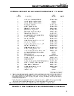
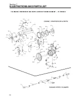
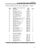
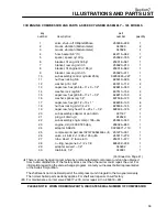
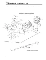
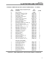
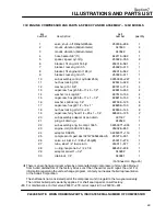
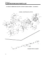
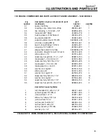
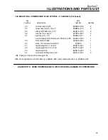
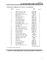
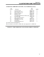
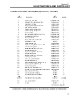
7.3C ENGINE, COMPRESSOR AND PARTS & SPEED CYLINDER ASSEMBLY -- 185H MODELS
key
part
number
description
number
quantity
1
valve, shut---off 3/8nptx3/8hose
250008---266
1
2
mount, vibration (50durometer)
047630
4
3
mount, vibration (50durometer)
047628
4
4
hose,heater 5/8” (ft)
842115---062
1
5
spacer, speed cyl. mtg.
250022---765
2
6
bracket, frt eng mnt 185 jd
250018---581
1
7
bracket, rear eng mnt rh
250020---310
1
8
bracket, frt engine mnt 185 jd
250018---582
1
9
bracket, rear eng mnt lh
250020---311
1
10
sub assembly,control cylinder 250q
02250045---227
1
11
nut,hex locking 5/8
825510---329
4
12
washer, pl b r 5/8”
837210---112
4
13
capscrew, hex gr5 5/8---11 x 3---1/2”
828610---350
4
14
washer, lock reg 5/8”
837510---156
4
15
capscrew, hex gr8 5/8---11 x 1---1/2”
828210---150
4
16
washer, sprlock reg 1/2”
837508---125
8
17
capscrew, hex gr8 1/2---13 x 1”
828208---100
8
18
nut,hex locking pltd 1/4---20
825504---145
2
19
capscrew, ferry head 1/4---20 x 1---1/4”
828404---125
2
20
sub assembly,adapter oil pan drain
221187
1
21
plug, oil drain---jd
242529
1
22
sub assembly,eng. & compr. 185h
02250071---603
1
23
engine, dsl jd 4.039 185 dpq
250026---853
1
24
adapter, SAE #4
02250071---119
1
25
compressor & part,dxx102147b352s43ac
(I)
251270---001
1
26
valve, air inlet 2---1/2 85---125q
(II
)
250017---279
1
27
tube, steel 1/4” fuel return
250011---577
1
28
o---ring,neoprene 3---1/2 x 1/8
826202---238
1
29
adapter, swivel 1---1/2”
040292
1
30
drainlock, 1/4”
040061
1
(Continued on Page 45)
(I)
There is an exchange program whereby a remanufactured compressor unit can be obtained
from Sullair distributors or the factory at less cost than the owner could repair the unit. For
information regarding the unit exchange program, contact your nearest Sullair representative
or the Sullair Corporation.
The shaft seal is not considered part of the compressor unit in regard to the two year warranty.
The normal Sullair parts warranty applies. For shaft seal repairs consult factory.
(II)
For maintenance on inlet valve 250017---279, order repair kit no. 250019---451.
PLEASE NOTE: WHEN ORDERING PARTS, INDICATE SERIAL NUMBER OF COMPRESSOR
Содержание 175
Страница 6: ...NOTES ...
Страница 18: ...Section 2 DESCRIPTION 12 Figure 2 4A Control System with Piping and Instrumentation 175 185 Models ...
Страница 19: ...Section 2 DESCRIPTION 13 Figure 2 4B Control System with Piping and Instrumentation 185H Models ...
Страница 22: ...Section 2 DESCRIPTION 16 Figure 2 7 Electrical System ...
Страница 40: ...Section 7 ILLUSTRATIONS AND PARTS LIST 34 7 3A ENGINE COMPRESSOR AND PARTS SPEED CYLINDER ASSEMBLY 175 MODELS ...
Страница 42: ...Section 7 ILLUSTRATIONS AND PARTS LIST 36 7 3A ENGINE COMPRESSOR AND PARTS SPEED CYLINDER ASSEMBLY 175 MODELS ...
Страница 44: ...Section 7 ILLUSTRATIONS AND PARTS LIST 38 7 3B ENGINE COMPRESSOR AND PARTS SPEED CYLINDER ASSEMBLY 185 MODELS ...
Страница 46: ...Section 7 ILLUSTRATIONS AND PARTS LIST 40 7 3B ENGINE COMPRESSOR AND PARTS SPEED CYLINDER ASSEMBLY 185 MODELS ...
Страница 48: ...Section 7 ILLUSTRATIONS AND PARTS LIST 42 7 3C ENGINE COMPRESSOR AND PARTS SPEED CYLINDER ASSEMBLY 185H MODELS ...
Страница 50: ...Section 7 ILLUSTRATIONS AND PARTS LIST 44 7 3C ENGINE COMPRESSOR AND PARTS SPEED CYLINDER ASSEMBLY 185H MODELS ...
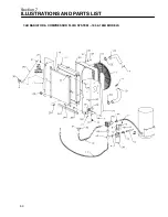
Страница 52: ...Section 7 ILLUSTRATIONS AND PARTS LIST 46 7 4A RADIATOR COMPRESSOR FLUID SYSTEM 175 MODELS ...
Страница 54: ...Section 7 ILLUSTRATIONS AND PARTS LIST 48 7 4A RADIATOR COMPRESSOR FLUID SYSTEM 175 MODELS ...
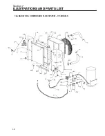
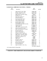
Страница 56: ...Section 7 ILLUSTRATIONS AND PARTS LIST 50 7 4B RADIATOR COMPRESSOR FLUID SYSTEM 185 185H MODELS ...
Страница 58: ...Section 7 ILLUSTRATIONS AND PARTS LIST 52 7 4B RADIATOR COMPRESSOR FLUID SYSTEM 185 185H MODELS ...
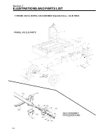
Страница 60: ...Section 7 ILLUSTRATIONS AND PARTS LIST 54 7 5 FRAME AXLE PARTS AXLE ASSEMBLY Exploded View ALL MODELS ...
Страница 62: ...Section 7 ILLUSTRATIONS AND PARTS LIST 56 7 5 FRAME AXLE PARTS AXLE ASSEMBLY Exploded View ALL MODELS ...
Страница 66: ...Section 7 ILLUSTRATIONS AND PARTS LIST 60 7 6A RECEIVER PNEUMATIC CONTROL SERVICE VALVE 175 185 MODELS ...
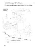
Страница 68: ...Section 7 ILLUSTRATIONS AND PARTS LIST 62 7 6B RECEIVER PNEUMATIC CONTROL SERVICE VALVE ASSEMBLY 185H MODELS ...
Страница 70: ...Section 7 ILLUSTRATIONS AND PARTS LIST 64 7 6B RECEIVER PNEUMATIC CONTROL SERVICE VALVE ASSEMBLY 185H MODELS ...
Страница 76: ...Section 7 ILLUSTRATIONS AND PARTS LIST 70 7 9A ELECTRICAL PARTS ENGINE OIL PRESSURE SWITCH ASSEMBLY 175 MODELS ...
Страница 78: ...Section 7 ILLUSTRATIONS AND PARTS LIST 72 7 9B ELECTRICAL PARTS 185 185H MODELS ...
Страница 80: ...Section 7 ILLUSTRATIONS AND PARTS LIST 74 7 10 INSTRUMENT PANEL PARTS ALL MODELS ...
Страница 82: ...Section 7 ILLUSTRATIONS AND PARTS LIST 76 7 11A AIR INLET AND EXHAUST 175 MODELS ...
Страница 84: ...Section 7 ILLUSTRATIONS AND PARTS LIST 78 7 11B AIR INLET AND EXHAUST 185 185H MODELS ...
Страница 86: ...Section 7 ILLUSTRATIONS AND PARTS LIST 80 7 12 FUEL TANK CONNECTIONS ALL MODELS ...
Страница 88: ...Section 7 ILLUSTRATIONS AND PARTS LIST 82 7 13A CANOPY PARTS 175 MODELS ...
Страница 90: ...Section 7 ILLUSTRATIONS AND PARTS LIST 84 7 13B CANOPY PARTS 185 185H MODELS ...
Страница 92: ...Section 7 ILLUSTRATIONS AND PARTS LIST 86 7 14 DECALS ...
Страница 94: ...Section 7 ILLUSTRATIONS AND PARTS LIST 88 7 14 DECALS ...
Страница 96: ...Section 7 ILLUSTRATIONS AND PARTS LIST 90 7 14 DECALS ...
Страница 99: ......