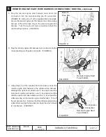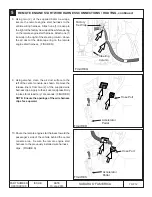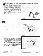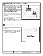
background image

11 OF 12

ISSUE

-

DATE

10 Jan 2018

SUBARU OF AMERICA

PART NUMBER

H001SXC100

SYSTEM REGISTRATION

10

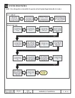
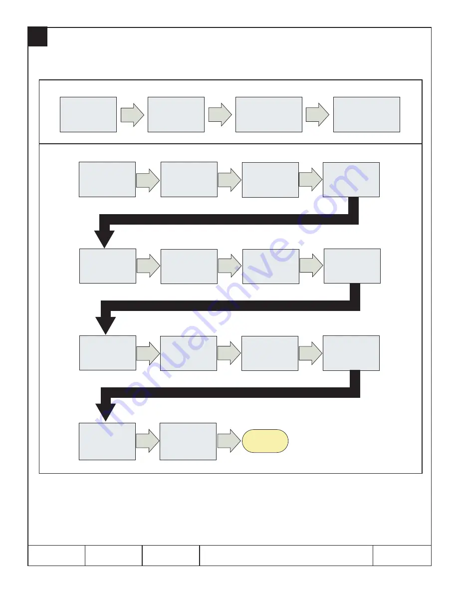
DST-i SETUP

REGISTRATION

Insert an ignition key

into the ignition 

cylinder and turn to  

Press and hold the DST-i 

“B” and “A” buttons 

simultaneously for 

approximately 5 seconds 

to enter stand alone mode

DST-i screen will 

display "Press YES if 

it is a smart system, 
otherwise press NO.

Using the arrows 

on the DST-i, select 

“Name”

DST-i screen will 

display "Execute 

Remote Engine Start 

CM Registration? 

Press YES or NO

Registration

Complete 

PRESS

A

PRESS

A

PRESS

A

PRESS

A

PRESS

A

PRESS

A

PRESS

A

PRESS

A

Plug the DST-i 

Using the arrows on the 

DST-i, select Diagnostic

and Press “A” to proceed 

to Registration

diagnostic plug

diagnostic connector 

into the vehicle’s

Using the arrows 

on the DST-i, select 

“Ascent”

Using the arrows 

on the DST-i, select 

“Model year”

Using the arrows on 

the DST-i, select the 

vehicle model year 

“XXMY”

Using the arrows 

on the DST-i, select 

“Immobilizer”

Using the arrows 

on the DST-i, select 

“NO”

DST-i screen will 
display "Check if 

Ignition SW is 

turned ON.”

Using the arrows 

on the DST-i, select 

“YES”

Using the arrows 

on the DST-i, select 

“Remote Engine Start 

CM Registration”

DST-i screen will 

display "Successful 

[Remote Engine Start 

CM Registration] 

Press OK”

Using the arrows 

on the DST-i, select 

“YES”

PRESS

A

PRESS

A

Using the arrows 

on the DST-i, select 

“OK”

the ON position


NOTE:  Once the Ignition is turned ON, the system will exit System Registration after 2 minutes.

Содержание H001SXC100

Страница 1: ...empt to start the engine three 3 additional times The system will not attempt to restart the engine if it determines a vehicle malfunction is preventing it from starting If the engine does not start a...

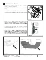
Страница 2: ...l carefully remove the left side dashboard panel by starting at the top and working downward to disengage six 6 pressure clips FIGURE B 3 Using a Phillips screwdriver remove one 1 Phillips screw secur...

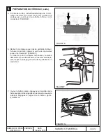
Страница 3: ...bolster FIGURE E 6 Remove the lower airbag knee bolster Using a pick tool disengage the yellow connector lock by lifting upward FIGURE F Using a panel removal tool carefully lift upward to unplug the...

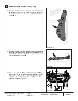
Страница 4: ...FIGURE J 9 Using a panel removal tool carefully remove the passenger s side ornament panel by lifting upward to disengage eight 8 pressure clips and then pulling toward the rear of the vehicle FIGURE...

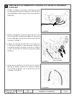
Страница 5: ...hicle s wire harness with breakaway tape near the upper driver s side kick panel area FIGURE L 3 When the vehicle s 4 pin and 2 pin pre fit connectors are free from the breakaway tape unplug and disca...

Страница 6: ...6 Plug the remote engine start harness 6 pin connector into the corresponding pre fit ignition connector FIGURE O 7 Using three 3 of the supplied 39cm tie wraps secure the remote engine start harness...

Страница 7: ...he air duct surface to the left of the center console as shown Remove the release liners from two 2 of the supplied wire harness clips Apply to the air duct and press firmly in place for at least ten...

Страница 8: ...IGURE V S U B A R U P P TD 2 0 C 1 6 0 1 0 0 9 9 REMOTE ENGINE START ECU MOUNTING 6 1 Locate the glove box inner cover and carefully pull back the insulation pad from the top and back areas as shown U...

Страница 9: ...shwall when reassembled 4 Plug the remote engine start harness 12 pin and 8 pin connectors into the remote engine start ECU FIGURE W 5 Secure the remote engine start harness to the wire harness clips...

Страница 10: ...ight side dashboard panel by engaging the six 6 pressure clips 8 Re install the glove box and strut 9 At the end of the installation insert the Quick Reference Cards into the Owner s Information Kit S...

Страница 11: ...ST i select Diagnostic and Press A to proceed to Registration diagnostic plug diagnostic connector into the vehicle s Using the arrows on the DST i select Ascent Using the arrows on the DST i select M...

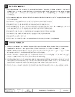
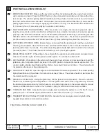
Страница 12: ...should honk six 6 times The vehicle should not start with any door or rear gate opened 4 BRAKE PEDAL SAFETY While sitting in the vehicle with the engine hood all doors and rear gate closed activate t...

Страница 13: ...or starts and stalls the remote engine start system will power off and then attempt to start the engine three 3 additional times The system will not attempt to restart the engine if it determines a ve...

Страница 14: ...ez d licatement le panneau du c t gauche du tableau de bord en partant du haut et en descendant pour lib rer les six 6 attaches pression FIGURE B 3 l aide du tournevis Phillips retirez une 1 vis Phill...

Страница 15: ...r c t conducteur FIGURE E 6 Retirez le prot ge genoux coussin gonflable inf rieur l aide du poin on lib rez le verrou du connecteur jaune en le soulevant FIGURE F l aide de l outil de d pose de pannea...

Страница 16: ...l aide de l outil de d pose de panneau enlevez d licatement le panneau de garniture c t passager en le soulevant pour lib rer les huit 8 attaches pression puis en tirant vers l arri re du v hicule FIG...

Страница 17: ...e pr s du haut du panneau de seuil c t conducteur FIGURE L 3 Lorsque les connecteurs pr mont s 4 broches et 2 broches sont d gag s du ruban d tachable d branchez le cavalier connecteur homologue 2 bro...

Страница 18: ...au du d marreur distance dans le connecteur d allumage pr mont correspondant FIGURE O 7 l aide de trois 3 des attaches autobloquantes de 39 cm fournies fixez le faisceau du d marreur distance au faisc...

Страница 19: ...d air gauche de la console centrale comme sur l illustration Retirez les endos adh sifs de deux 2 des attaches de faisceau de c blage fournies Appliquezcelles cisurlacanalisationd airetappuyez fermeme...

Страница 20: ...LLATION DE L UCE DU D MARREUR DISTANCE 6 1 Rep rez le couvercle int rieur de la bo te gants et retirez d licatement le matelas isolant sur le dessus et l arri re comme sur l illustration Avec de l alc...

Страница 21: ...cteurs 12 broches et 8 broches du faisceau du d marreur distance dans l UCE du d marreur distance FIGURE W 5 Fixez le faisceau du d marreur distance aux attaches de faisceau de c blage FIGURE W REMARQ...

Страница 22: ...tallez la bo te gants et le support 9 la fin de l installation glissez la Carte de r f rence rapide dans le dossier du propri taire D MARRAGE DU SYST ME 1 Une fois toutes les connexions termin es rebr...

Страница 23: ...c and Press A to proceed to Registration diagnostic plug diagnostic connector into the vehicle s Using the arrows on the DST i select Ascent Using the arrows on the DST i select Model year Using the a...

Страница 24: ...entir six 6 fois Le v hicule ne doit pas d marrer si l une des portes ou le coffre sont ouverts 4 S CURIT DE LA P DALE DE FREIN Pendant que vous tes assis dans le v hicule et que le capot toutes les p...

Отзывы: