background image

Page 9

Electronics

Induction Range (IR) Series

Induction Range (IR) Series

2-9

#827176 - Revision A.2 - September, 2017

Diagnostic Mode

Used to test the cooktop systems, view stored error codes, view real-time readings from system sensors, and to
enter/exit Showroom mode.

Entering Diagnostic Mode

Must be entered from Lock Mode.

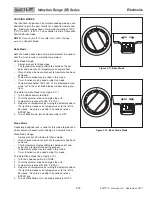
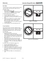
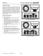
Touch and hold the 

“+” 

pad and 

“-” 

pad for 5 seconds.

After 5 seconds enters LED test, alerting the user to remove their fingers.

If another key pad sensor detects a signal, Diagnostic Mode does not engage. 

If either the 

“+” 

or 

“-” 

pad is not released after 7 seconds, Diagnostic Mode does not engage.

Power to all coil assemblies is disabled.

After 60 seconds if no input is detected the control returns to Lock Mode.

ALL OFF

pad exits Diagnostic Mode and the control returns to Lock Mode.

There are no audible signals.

To step through the various tests touch the 

“+” 

and 

“-” 

pads.

Rear left 

“…” 

display advances one LED for each test to identify which test is being performed.

Diagnostic Mode Procedures

LED Test

All LED indicators for all control zones are on. 

LOCK

LED, all segments of the Timer display, 

HOT

display

and all 

BOOST

LEDs are on.

Front left control zone 

SIM/MLT

“…” 

or 

HI

pads cycles LEDs to on, dim, or off.

One 

“.” 

displayed on the left rear control zone indicates LED test is running.

“+” 

pad engages Unit Reconfiguration.

Unit Reconfiguration and Unit Derating

b1. Unit Reconfiguration - software version below version V.10

Touch 

“+” 

pad during the LED test. 

Two 

“.” 

are displayed on left rear control zone.

CF

is displayed in the 2-digit display.

Only one 

“.”

is displayed in the front left control zone.

Press and hold 

“+” 

and 

“-” 

pads together for 3 seconds activates the unit reconfiguration.

Acceptance beep is sounded after the requisite press-and-hold and the cooktop resets.

“-” 

pad engages LED Test.

“+” 

pad engages Control Temperature Readout.

b2. Fully Rated to Derated and Unit Reconfiguration - software version V.10 or higher

Touch 

“+” 

pad during the LED test. 

Two 

“.” 

are displayed on left rear control zone.

CF

is displayed in the 2-digit display.

Front left control zone 

SIM/MLT

, or 

HI

pads cycles between “fully rated,” or “derated” mode.

If first 

“.”

is brighter then the second 

“.”

on the front left control zone, unit is in “fully rated” mode.

If second 

“.”

is brighter then the first 

“.”

on the front left control zone, unit is in “derated” mode.

Press and hold 

“+” 

and 

“-” 

pads together for 3 seconds activates the unit reconfiguration, and sets the

unit in the “fully rated” or “derated” mode.
Acceptance beep is sounded after the requisite press-and-hold and the cooktop resets.

“-” 

pad engages LED Test.

“+” 

pad engages Control Temperature Readout.

NOTES:

Reconfiguring the unit resets the communication between the generator and control board software.

Reconfiguring the unit is recommended to be performed for any electronic communications error and after
replacing a generator or control board.
The power rating of the unit does not have to be changed to perform unit reconfiguration.

Left rear 

“.” 

remains at two and CF is displayed in the 2-digit display during the unit reconfiguration.

After replacing a generator the 

LOCK

light does not illuminate. The unit is locked.

Содержание Wolf IR Series

Страница 1: ...Controls Operation 6 subzero com 800 222 7820 IR Induction Range Service Manual ...

Страница 2: ...sets power to level 1 HI sets power to level 10 BOOST sets power to Boost and adjusts adjacent power levels as required by the induction power sharing scheme Toggles Boost off if already engaged BRIDGE Activates vertically adjacent coil assemblies to same power level BRG Activates horizontally adjacent coil assemblies to same power level ALL BRIDGE Activates the four adjacent coil assemblies on th...

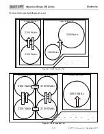
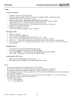
Страница 3: ...M HI 1400 Watts B O O S T B O O S T Figure 2 1 IR304 Induction Top B R I D G E 2100 Watts 2100 Watts 2600 Watts ALL OFF LOCK TIMER _ OFF ON HI MLT BOOST OFF ON SIM HI OFF ON SIM HI BOOST BRIDGE OFF ON SIM HI 2100 Watts 2100 Watts OFF ON SIM HI BOOST BRIDGE ALL BRIDGE BRG BRG Generator Board 1 Generator Board 2 Generator Board 3 B O O S T B O O S T B O O S T Figure 2 2 IR365 Induction Top B R I D G...

Страница 4: ...sly for additional 3 intervals the count rate increases again 6 A continuously held or increases in this manner 00 01 02 03 04 05 10 15 20 30 40 50 60 70 80 90 99 Ending the Timer At 60 seconds the One Minute Remaining beep sounds At 00 the Timer Complete beep sounds until acknowledged Touch of the TIMER or pad stops Timer Complete beep and clears the display Touch of the pad adds time to the time...

Страница 5: ...nnunciator sounds Failure beep if any control zone is active when trying to enter Lock Mode Exiting Lock Mode Touch and hold the LOCK pad for 3 seconds If LOCK pad is held for more than 10 seconds cooktop relocks Annunciator sounds Acceptance beep to indicate Lock Mode has been exited LOCK LED turns off and control zones enter Idle Mode Valid key presses in Lock Mode LOCK pad for exiting Lock Mode...

Страница 6: ... zone returns to Idle Mode During the 30 second wait the LEDs for that control zone flash the power level selected If a bridge is activated and a pan is detected on one control zone but not all control zones being bridged the LEDs for the unsensed control zones flash the power level that has been selected If after 2 minutes one or more of the control zones in the bridge still does not sense a pot ...

Страница 7: ... recent command takes precedence activating the new bridge and shutting off the old bridge Boost Operational Mode Notes See Figures 2 1 and 2 2 During Boost coil assemblies on the same generator board have their power level adjusted If Boost is activated a second touch of the BOOST pad deactivates Boost returning the power level to Hi Boost can not be activated for control zones in a bridge Boost ...

Страница 8: ...e also used in Diagnostic Mode When an error is displayed it is accompanied by the Failure beep Active error is one that is currently being displayed other errors can be debounced and logged while another error is active Some errors are only displayed when a pad in the affected control zone is touched Showroom Mode Notes and Restrictions in Showroom Mode Full user functionality with no power being...

Страница 9: ...re displayed on left rear control zone CF is displayed in the 2 digit display Only one is displayed in the front left control zone Press and hold and pads together for 3 seconds activates the unit reconfiguration Acceptance beep is sounded after the requisite press and hold and the cooktop resets pad engages LED Test pad engages Control Temperature Readout b2 Fully Rated to Derated and Unit Reconf...

Страница 10: ...mmed 1 2 or 3 to indicate heat sink number with one on to indi cate which heat sink temperature is displayed First LED is generator board 1 Second LED is generator board 2 Third LED is generator board 3 A touch of the pad engages the Control Temperature Readout A touch of the pad engages the Coil Temperature test e Coil Temperature Test Touch pad during the Heat Sink Temperature test Five are disp...

Страница 11: ... codes Touch and hold TIMER pad for 5 seconds to clear error code history Clearing the error code history is only possible if at least one error was logged Clearing the error code history is confirmed by a double beep If an error is currently present when the log is cleared it immediately regenerates an error code pad engages the Coil Temperature test pad engages Showroom Mode menu g Showroom Mode...

Страница 12: ...e level Power level 1 for low power level 5 for medium and power level 10 for high Touch the front left control zone MLT SIM pad or HI pad to adjust the volume up or down As the volume is adjusted the annunciator sounds a tone at the newly selected setting A touch of the pad advances the user options mode to Annunciator Frequency b Annunciator Frequency Two displayed on of the left rear control zo...

Страница 13: ...k See Figure 2 5 Touch the CLOCK key on ECH CLOCK flashes on 1 and off Touch the up or down arrow key to increase or 2 decrease the time Touch the CLOCK key or ENTER key to set the 3 clock Two beeps sound when the time has been entered NOTE Time changes from am to pm by passing the 12 00 mark Oven Timer The oven timer operates independently from the oven controls Once a time is set in hours and mi...

Страница 14: ...ey or allow the clock to time out 3 and set by default Clock Standby Power The range is shipped in standby power mode which dis ables the clock approximately 10 minutes after the cool ing fan operation shuts off or the last key stroke on the ECH The clock illuminates after any touch of the con trols or oven use To enter Clock Standby Power See Figure 2 9 Touch and hold the CLOCK key for five secon...

Страница 15: ...ature is preset to 350 F 175 C 3 Adjust oven temperature by turning the selector knob to 4 the right to increase oven temperature or to the left to decrease Oven turns on after 2 seconds or press ENTER key To exit Bake Mode turn knob assembly to OFF 5 Stone Mode A specially designed rack is used for this mode to produce a an environment necessary for baking on a ceramic stone Stone Mode Usage Alwa...

Страница 16: ...en cavity Uniform air move ment makes it possible to cook on all six rack levels simultaneously Convection Mode Usage Always preheat for Convection mode The temperature display alternates between the set point and actual oven temperatures during preheat Oven chimes when oven preheat temperature has been achieved Temperature probe may be used in this mode Timer function may be used during this mode...

Страница 17: ... to the left to decrease Oven turns on after 2 seconds or press ENTER key To exit Convection Bake Mode turn knob assembly 5 to OFF Convection Broil Mode Intense radiant heat from broil element browns and sears the surface of the food Both convection fans circulate hot air around the food This mode shortens broiling times for thicker foods Convection Broil Mode Usage Never preheat for Convection Br...

Страница 18: ...onds or press ENTER key To exit Convection Roast Mode turn knob assem 5 bly to OFF Roast Mode Both bake and broil elements are used to heat and cycle to maintain temperature Roast Mode Usage Always preheat for Roast mode The temperature display alternates between the set point and actual oven temperatures during preheat Oven chimes when oven preheat temperature has been achieved Temperature probe ...

Страница 19: ...t allow the temperature to be set above 110 F 43 3 C If the oven temperature is above 130 F 55 C HOT is indicated on the control panel The oven door should be opened to allow the oven to cool down below 120 F 50 C to prevent the destruction of the yeast Oven temperature is preset at 85 F 29 C The temperature display alternates between set temperature and PrF To initiate PROOF Feature the oven must...

Страница 20: ...urn the knob assembly 10 to OFF Probe Feature The probe measures internal temperature of food without opening the oven door Probe Usage To change the temperature setpoint during probe mode you must exit probe mode and restart with a new probe setpoint Use the desired cooking mode as recommended Set the probe for 5 less the desired temperature The temperature rises during the rest time To initiate ...

Страница 21: ... food soil is burned off leaving some white ash residue Self Clean Feature Usage Oven door remains locked until temperature inside has cooled to below 300 F 150 C Oven racks rack guides broiler pan and any uten sils in the oven must be removed before self clean ing On double oven models only one cavity can be cleaned at a time On double oven models when one oven is being cleaned the other oven can...

Страница 22: ... after the last key stroke To clear error codes once unit has been repaired press the CLEAR key while in Diagnostic Mode To exit Diagnostic Mode press the ENTER key The ambient cavity temperature is displayed in the selector knob window The software version is displayed in the Time of Day digits To initiate Diagnostic Mode See Figure 2 25 Knob assembly must be in the OFF position 1 Press and hold ...

Отзывы: