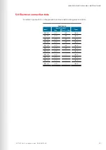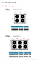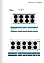
741
480
741
10
4
25
0
61
© STULZ S.p.A. – all rights reserved EN/06.2016/i01
WPA ExPlOrEr OrIGINAl INSTrUCTIONS
6.9 Opening the electric cabinet
The switched ON main switch prevents opening the doors of the power section (2 doors). Only, if
the main switch is in position "0" you can open the doors.
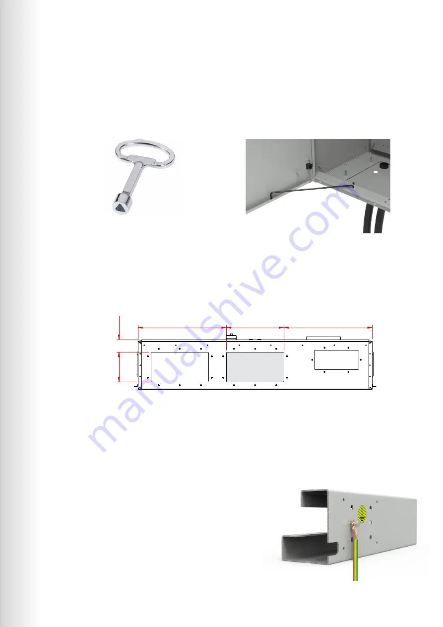
The doors of the electrical cabinet can be opened by the key which is delivered with the chiller.
After opening the doors their position must be fixed with the two supplied distance pieces to
prevent unexpected movements of the doors caused by outer influences.
6.10 Position of the electrical connections
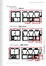
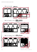
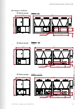
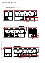
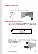
The electrical connection lines can be introduced into the electric cabinet from the bottom. The
position of the opening for the wires can be adjusted within the range of the panel shown in the
following views.
7mm triangular key
Cuttable
removable
pannel
Front side
The power supply system on site and the pre-fuses must be designed for the total current of the
unit ("5.4 Technical Data" at page 40). Make sure that the power supply corresponds to the
indications on the rating plate and that the tolerances according to the "5.1 Application limits" at
page 34
are not exceeded.
Route the electric cable into the electrical cabinet from below and connect the PE conductor at
the PE rail and the three phases to the main switch, in accordance with the wiring diagram (part
of the unit documents). Use a cable gland on
the bottom panel to fix the cable.
Connect the ground cable to the base of the
chiller using on the designated position iden-
tified by the grounding symbol.
Use screw with a minimum diameter Ø 8 mm.
The cable must contain a terminal lug.

