75
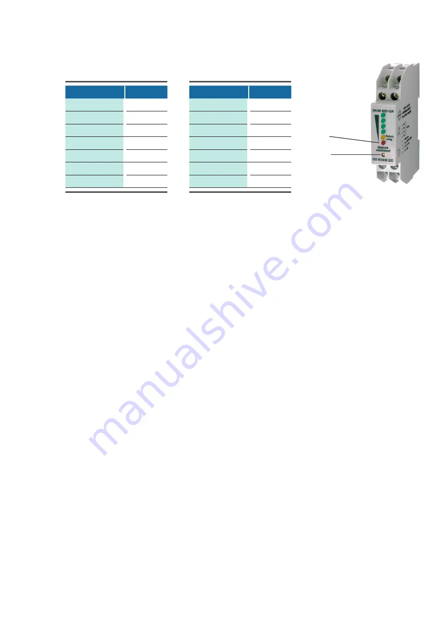
Modell
V
min
[m³/h]
E_O 4702 A__
30
E_O 5102 A__
30
E_O 6002 A__
35
E_O 6602 A__
40
E_O 7402 A__
45
E_O 8002 A__
50
E_O 8702 A__
55
Modell
V
min
[m³/h]
E_O 9602 A__
60
E_O 10202 A__
65
E_O 11102 A__
70
E_O 11502 A__
75
E_O 12602 A__
80
E_O 13102 A__
85
E_O 14102 A__
90
© STULZ GmbH – all rights reserved EN/09.2019/G41
cybercool 2 screw original insTrUcTions
6.6 Commissioning of the refrigerant circuits
• Check the current consumption of compressor 1 and of the condenser fans comparing it with the values in
the technical data.
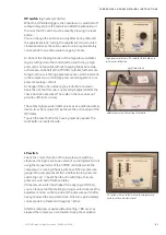
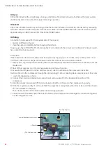
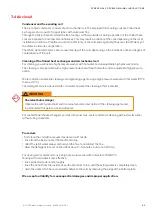
• Check the oil level at compressor 1 in respect of the right level. The oil sight glass is installed at the com
-
pressor and points to the condenser coils. After having removed the compressor cabinet panels of the left
unit side it can be read with the help of an electric torch and a mirror angled by 45 degrees.
The oil level should be between the lower quarter and the upper quarter of the sight glass.
comp 2 hand 1
comp 2 handon 0
• Now adjust the water flow by means of a regulating valve or a speed controlled pump to the necessary
value for standard operation. A speed controlled pump can not be controlled by the C7000 controller and
requires an external control.
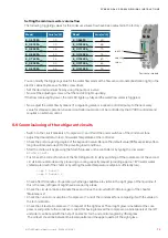
Setting the minimum water volume flow
The following triggering values for the minimum volume flow have been adjusted in the factory:
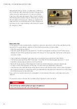
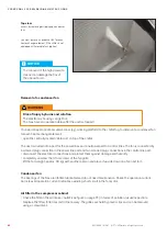
red LED
adjusting
screw
flow sensor module
You can modify the triggering value for the water flow alarm at the flow sensor module (illustration right) in the
electric cabinet by means of a little screw driver.
• Set the desired minimum flow by using the pump or a valve.
• Now set the adjusting screw so, that the red LED lights up dimly.
If the flow rate is slightly lower, the red LED lights up fully and the water flow alarm is triggered.
• Switch on the cirucit breakers of compressor 1 and 2 and the power switches of the condenser fans.
• Adjust the desired return resp. flow water temperature at the controller.
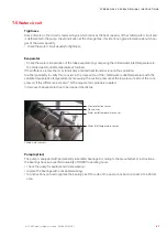
• Check the prerun opening degree of the expansion valve. Reduce the default value (30%) especially after a
long downtime and adapt it to the prevailing load conditions.
• Start the chiller unit by pressing the Start/Stop-key on the controller or by typing the command:
state start.
• First check the correct function of the first refrigerant circuit by switching off the compressor of the second
circuit in manual mode and by producing a cooling capacity request (providing approx. 18°C warm water
chilled water inlet of the chiller or by setting the water temperature setpoint sufficiently low).
• Check after 20 minutes of operation, whether gas bubbles are visible in the sight glass of the liquid line. If
this is the case, refrigerant might have escaped by a leak.
• Check the circuit on leaks, eliminate these and top up the circuit with R134a in regard of the chapter
"Maintenance".
Model
V
min
[m³/h]
Model
V
min
[m³/h]
Содержание CyberCool 2
Страница 4: ...4 4 EN 09 2019 G41 STULZ GmbH all rights reserved CYBERCOOL 2 SCREW ORIGINAL INSTRUCTIONS...
Страница 101: ......

