background image

E/0310/

50

/12

Actual value "Temperature"

Actual value "Humidity"

Setpoint "Temperature"

Setpoint "Humidity"

Limit value  "Room tempera-
ture too high"

Limit value "Room tempera-
ture too low"

Limit value "Room humidity 
too high"

Limit value "Room humidity 
too low"

Valve modulating time (in 
seconds)

Compressor restart delay

CW-valve start value

1. Compressor start value

Proportional range of CW- 
valve

Hysteresis of compressors

        ...1s...        alarm reset

Further Functions

Display

Meaning

Menu item

1

2

3

4

5

6

7

8a

8b

9a

9b

10a

10b


enter mode

modification of values by


and

leaving the enter mode
 

 with

+ PASSWORD 

Содержание CompTrol 1002

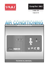
Страница 1: ...CompTrol 1002 AIR CONDITIONING Index 50 Issue 3 10 MICROPROCESSOR TECHNICAL MANUAL...

Страница 2: ......

Страница 3: ...ocessor Board C1002 28 7 3 Bus connection 30 7 4 Connection Diagram for Sequencing at the Processor Board 32 8 Speci cations of the Extension Card 1b 33 8 1 Technical Data Extension Card 1b 34 8 2 Con...

Страница 4: ...ed water CW units or units with a 2 stage compressor can be controlled A 2 unit sequencing is also included Functions such as cooling reheat humidi cation and dehumidi cation are continuously controll...

Страница 5: ...Elements Alarm reset START STOP key Right arrow key Down arrow key Up arrow key 4 digit LED Display Connection board DIP switch 1 4 Rear Plate Face Plate Status cooling Status reheat Status humidi ca...

Страница 6: ...rsion 2 1 When the sequencing is active i e menue point 24 0 the start of the stand by unit can be chosen by this switch ON No start by passing over a limit value OFF Start of stand by unit in additio...

Страница 7: ...d by an R DIP switch 4 can be switched over any time even during controller operation Function of switch is valid without further measures Membrane Keys Start Stop Key Operation mode start and stop ar...

Страница 8: ...enu Items 2 to 24 The enter mode for these menu items is activated by pressing the key After pressing this key there is a request for entering in the password Enter Mode Being in the enter mode you ca...

Страница 9: ...he power supply the cont roller will be in this operation mode again after the restart Three possibilities of how the unit has been stopped exist Display 1 Start Stop Key local mode 2 Remote On Off re...

Страница 10: ...ROM the following symbol appears in the display during the initial phase about 1 second The standard values of the program memory EPROM are loaded into the EEPROM and into the RAM During this procedur...

Страница 11: ...atur sensor adjustment CPU address Dehumidi cation hysteresis Dehumidi cation start value Humidi cation hysteresis Humidi cation start value Reheat 2 start value Reheat 1 and 2 hysteresis Limit value...

Страница 12: ...Room humidity too high Limit value Room humidity too low Valve modulating time in seconds Compressor restart delay CW valve start value 1 Compressor start value Proportional range of CW valve Hysteres...

Страница 13: ...alue Humidi cation start value Humidi cation hysteresis Dehumidi cation start value Dehumidi cation hysteresis CPU address Temperature sensor adjust ment Humidity sensor adjustment Unit start delay Fu...

Страница 14: ...units Actual opening degree CW valve Further Functions Menu item 23 24 25 The menu items 8a 11a and 25 are valid for CW units The menu items 8b 11b are valid for units with a compressor enter mode mod...

Страница 15: ...item Unit of temperature is C or F Humidity Setpoint Humidity setpoint is shown in this item High Temperature Limit value If the actual value temperature is rising up to this point an alarm Temperatur...

Страница 16: ...ng degree for dehumi di cation can be passed over when the CW valve s opening degree for cooling is increased b Units with Compressor Compressor Restart Delay In this item the restart delay in seconds...

Страница 17: ...ressor will be started The dehumidi cation function is stopped when temperature is less than 0 5 K 0 9R above the low temperature limit value It is enabled with a hysteresis of 0 5 K 0 9R Modi cation...

Страница 18: ...e to position of DIP switch 4 degrees Celsius or Fahrenheit By loading the basic program of the controller sensor adjustment is reset to zero Humidity Sensor Adjustment Humidity sensor adjustment can...

Страница 19: ...e setpoint is made using the follo wing formula SP Setpoint Actual Value x Integral Factor which results in Control Setpoint SP2 SP1 SP Item 23 Actual value a modi cation of setpoint in enter mode con...

Страница 20: ...I proportion is not desired the integral factor is set to zero A P controller exists and the control setpoint is equal to the setpoint Under the following circumstances the setpoint is immediately tak...

Страница 21: ...ating 2 is needed an extension board is installed on which one input and output are available for the sequencing This way the 2nd heating stage and the water detector input are available again on the...

Страница 22: ...unit can be continued in operation for a while The alarm relay is not activated These functions are only supervised in start mode Ultrasonic humidi er 5 S cm Filter Alarms Actual values are supervised...

Страница 23: ...larm Reset Alarms And Failures Resetting of alarms and failures can only be done in menu item 1 Warning Alarm Relay Inactive Press key and within 1 s later press key After that warning is reset and th...

Страница 24: ...ure Humidi er 20 S cm failure Conductivity meter 5 S cm Air ow 1 failure Air ow 2 failure Low pressure compressor 1 Low pressure compressor 2 Compressor 1 failure Compressor 2 failure Clogged lter Aux...

Страница 25: ...6 Control Diagram for CW Units Temperatur Control Diagram Temperature too low Temperature too high CW Cooling Setpoint Humidity Control Diagram Humidity too high Setpoint Humidity too low Humidi cati...

Страница 26: ...perature Control Diagram 1 Compressor 2 Compressor Numbers refer to the menu items Temperature too low Temperature too high Setpoint Humidity Control Diagram Humidity too high Setpoint Humidity too lo...

Страница 27: ...rmally open for alarm humidi cation 5 x triac 4 Amp 24 V fan valve or compressor and dehumidi cation saver circuit reheat 1 reheat 2 The consumer is connected to 24V 8 x 24 V AC 2 7 kOhm input resista...

Страница 28: ...sion card X10 at cable plug 6 3 0 8 X11 connection terminal 33 pins X12 extension plug 20 pins If an extension card is installed the inputs for Ultrasonic 5 S cm and Aux2 re are situated on the extens...

Страница 29: ...eper operation level When connection V is supplied by power the valve is closing If there is a power interruption to the valve the last operation level is xed The consumer is connected to 24V Examples...

Страница 30: ...ntroller can be integrated in the Stulz bus The driver module serves to properly adjust the C1002 as a bus participant in dependence of the position within the bus For a detailed description of the dr...

Страница 31: ...ers are set for a low bias The driver module has the following features 1 a static bus termination 120 Ohm which can be activated by a jumper 2 a circuit to set the bias for the bus By means of two ju...

Страница 32: ...24 V 0 V A1 Seq A2 30 17 20 21 29 3 2 1 ALARM 24 V 0 V 30 17 A1 Seq A2 E 0310 50 32 7 4 Connection Diagram for Sequencing at the Processor Board Remote On Off Aux 1 Heating 2 Unit 1 Unit 2 Remote On...

Страница 33: ...ector and Ultrasonic humidi er 5 S cm can only be detected on the extension board Operating Elements DIP Switches 1 6 DIP Switch 1 Con guration of a damper ON A damper is con gured Fan start is delaye...

Страница 34: ...ature Limit exists As soon as a voltage of 24 V is applied to this input the cooling is interrupted That means for CW version The CW valve closes Compressor version The compressors are switched off 12...

Страница 35: ...nnected to 24 V Compressor 2 Sequencing out Sequencing 24 V Damper Sequencing in high pressure comp 2 low pressure comp 2 Air ow module 2 Temperature limit Aux2 Firestat and smoke detector Ultrasonic...

Страница 36: ...RM 24 V 0 V 20 21 29 3 2 1 ALARM 15 11 12 15 11 12 24 V 0 V A1 Seq A2 A1 Seq A2 E 0310 50 36 8 3 Connection Diagram for Sequencing with Extension Card Unit 1 Unit 2 Extension 1b Extension 1b Remote On...

Страница 37: ...it value humidity too low 8a Valve modulating time 8b Compressor restart delay 9a CW valve start value 9b Compressor 1 start value 10a CW valve proportional range 10b Hysteresis compressors 11a Openin...

Страница 38: ...word is requested in enter mode The display shows To enter the password keys and must be pressed within 5 seconds Now the display ashes and the parameter can be modi ed Should a wrong key be pressed o...

Страница 39: ......

Отзывы: