/11.2015/
G17D
9
EN
4.4 Function
The A/C unit is exclusively operated by the controller in the front panel and the main switch (operable from outside
the unit) in the electric box.
In the air inlet a temperature/humidity sensor is located which provides the measured values for the temperature/
humidity control. In general the cooling is achieved by compressor operation in the refrigerant circuit. In the unit
version GE a direct cooling by a chilled water coil is also possible.
The A/C unit control is effected by the on board I/O controller. The operational conception is designed such as to
allow to control up to 19 units from one unit. These units can be installed separately with a maximum control line
length of 1000 m.
Dehumidification
To achieve a dehumidification, the electronic expansion valve is partially closed in the first step. The reduction of the
refrigerant mass flow makes the evaporation temperature drop, which lets the surface temperature in a part of the
evaporator fall below the dew point of the air. This causes dehumidification.
For a bigger dehumidification, the fan speed is reduced. With a constant cooling capacity, the temperature of the air
which flows through the heat exchanger coil, passes below the dew point. The moisture contained in the air conden-
ses on the heat exchanger gathers in the condensate pan and is carried away by the drain.
4.2 Intended use
This A/C unit is used to control room temperature and air humidity. The A/C unit is designed for indoor installation.
Any use beyond this is not deemed to be use as intended. STULZ is not liable for any damage resulting from such
misuse. The operator alone bears the risk.
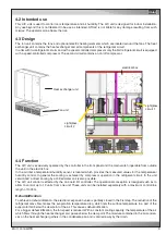
electrical box
sightglass,
circuit 2
Heat exchanger unit
Fan unit
4.3 Design
The fan unit contains the fans and optional electric heating elements which are located around the fans. The heat
exchanger unit contains the heat exchanger and all components of the refrigerant circuit.
In units with two refrigerant circuits and with a speed-controlled compressor only the first refrigerant circuit is equipped
with a speed-controlled compressor. The second circuit contains an on/off compressor.
sightglass,
circuit 1
Содержание ALR 1082 GE
Страница 39: ...11 2015 G17D 39 EN Size 7 control line power supply cable...
Страница 72: ......
Страница 75: ...05 2015 raisedfloor 3 EN Size 5 Size 7 drawing not yet available...
Страница 86: ......
Страница 91: ...5 10 2015 electric EN Wiring diagram of the circuit board...


