/11.2015/
G17D
19
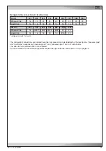
Baugröße
Anzahl
1 - 3
2
4
3
5
4
7
5
EN
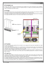
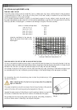
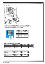
The heat exchanger unit and fan unit may be bolted
together, to prevent a move of both parts to each other
(e.g. in case of a shock from the front).
The screws and washers are included, drill holes are
existant, appropriate cage nuts are already installed in
the fan unit.
The M10 screws must be inserted in the lower cross bar
on the front side of the heat exchanger unit from above.
The number of screws varies with the size:
Size
Number
Detail drawing
Bolting of heat exchanger unit and fan unit
drill hole
cage nut
Содержание ALR 1082 GE
Страница 39: ...11 2015 G17D 39 EN Size 7 control line power supply cable...
Страница 72: ......
Страница 75: ...05 2015 raisedfloor 3 EN Size 5 Size 7 drawing not yet available...
Страница 86: ......
Страница 91: ...5 10 2015 electric EN Wiring diagram of the circuit board...

