/11.2015/
G17D
21
A-Gerät
532
602
682
722
802
892
822
1082
1252
Druckleitung
16
22
22
22
22
22
22
22
22
Flüssigkeitsleitung
16
16
16
16
16
16
16
16
22
AS-Gerät
542
742
552
732
832
1092
1302
Druckleitung
16
18/22* 18/22* 18/22* 18/22*
22
22
Flüssigkeitsleitung
16
16
16
16
16
22/16*
22
EN
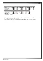
The refrigerant connections are located near the compressor and are labelled by the inscriptions "pressure pipe"
and "liquid pipe" respectively "pressure pipe 1" and "pressure pipe 2" etc. for 2-circuit units.
The lines to be connected have to be soldered.
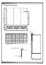
For the connection of the external pipework respect the pipe entrance area shown on top of page 20.
Refrigerant line connection (2 circuits) in mm
A unit
Pressure line
Liquid line
AS unit
Pressure line
Liquid line
*
refrigerant circuit 1/ circuit 2.
Содержание ALR 1082 GE
Страница 39: ...11 2015 G17D 39 EN Size 7 control line power supply cable...
Страница 72: ......
Страница 75: ...05 2015 raisedfloor 3 EN Size 5 Size 7 drawing not yet available...
Страница 86: ......
Страница 91: ...5 10 2015 electric EN Wiring diagram of the circuit board...


