8
INSTALLATION: ELECTRICAL CONNECTIONS / CASTERS / ADJUSTING LEVELERS
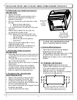
11. Display Case Start-Up
•
Remote Units: Case is hard-wired. When power is
supplied, case will power-up.
•
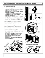
Self-Contained: Main Power switch on all units are
located at case rear, lower right.
•
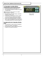
Self-Contained: Temperature Controller is located
at case rear, lower right.
•
Turn on the lights. Whether Remote or Self-
Contained, light switch is located on inside of case
at top right, from case rear.
•
All lights should come on at same time. First time
lighting may require short warm up period for
bulbs. Slightly dim/flickering of new bulbs is normal.
•
The lighting is wired in series so
all lights must be
plugged in or receptacles capped
to turn on.
12. Cases With Casters: Lock and Unlock
•
To lock casters, press down on lever.
•
To unlock casters, pull lever up.
•
See illustration at lower right.
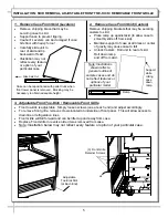
13. Cases With Levelers: Adjust Levelers
•
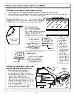
After case is in position, adjust case so it is level
and plumb (see illustration at right).
•
You may need to remove front and/or rear Toe-
Kick to access levelers.
•
Use adjustable wrench (and possibly a pry bar) to
adjust leveler.
•
Do not use pry bar on toe-kick (it may buckle).
•
Do not use pry bar on end panel (it may chip).
•
Use pry bar ONLY on base frame to avoid
damaging case.
•
Use a block to reach base frames with pry bar.
•
See illustrations below.
Pry Bar
Base
Frame
Leveler
Adjustable
Wrench
Toe-Kick
Block
Lo
ck
ed
Un
lo
ck
ed
Cap
Plug
Receptacle
Temperature
Controller
Main
Power
Switch
View of Case Rear, Self-Contained Unit
Rear Grille


