7
INSTALLATION: REFRIG. LINES / STUB-UPS / DRAINS / WIRING DIAGRAMS / VENTILATION
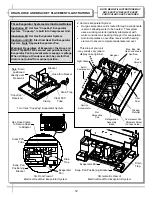
6. Refrigeration Line Stub-Up Connections
(Remote Units)
•
Remove front panel.
•
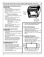
Refrigerant stub-up access opening is at the
front on the left hand side of the base (see
illustration at top-right).
•
Stub-up connections are accessed from inside
the case.
•
Remove interior ABS decks.
•
Remove fan shroud assembly.
•
Line connections are in the tub front, on the left
hand side
•
Remove foam material from the entry hole
provided in the tub drain trough.
•
Route refrigerant lines through access hole.
•
Run case-to-case connections through
cutouts in base.
•
Sweat the high and low pressure
connections.
•
Fill access hole with suitable filler to insure
watertight integrity of tub.
•
Illustration at top-right may not reflect every
feature or option of your particular case.
7. Refrigeration Drain Connection
(Remote Units)
•
Depending upon drain access needs, either front
or rear panel may be removed to gain access to
drain stub-up.
•
1.5” male PVC stub-up connection is under the
case on the right hand side.
•
Drain stub-up may be at case center in extended
length cases.
•
Connect tub drain to floor drain. Maintain
1/4”-fall per foot to provide proper drainage.
•
Illustration at top-right may not reflect every
feature or option of your particular case.
8. Evaporator Pan / Drain Position
(Self-Contained Units)
•
Remove rear panel (by removing screws).
•
Slide the Condenser Unit out from case.
•
Condenser Unit access is now available.
•
Insure that the evaporator pan is installed under
the PVC condensate drain trap.
•
Insure that the evaporator pan is plugged into the
receptacle inside base.
•
Lower rear panel back into place.
Refrigeration
Line
Stub-Ups
Access
Drain Stub-Up
(may be at case
center in extended
length cases)
10. Ventilation and Clearance
•
Self-Contained
refrigerated cases must
maintain airflow clearance of 6” (minimum) to
12” (recommended) at front and rear.
•
Restriction of air can void warranty.
•
Illustration below may not reflect every feature
or option of your particular case.
Check air grilles for obstructions.
Maintain airflow clearance of 6” (min.)
to 12” (recommended) at front & rear.
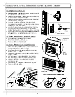
9. Electrical Wiring Diagram
•
Each case has its own wiring diagram
folded and in its own packet.
•
Wiring diagram placement may vary; it may
be placed near condenser fan cover,
ballast box, raceway cover, or other related
location.
•
See
Drain, Hose and Bracket Placement
section in Operating Manual for details.


