


14
MAINTENANCE: REFRIGERATION PKG., TEMP. CONTROLLER, EVAPORATOR PAN ACCESS
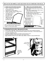
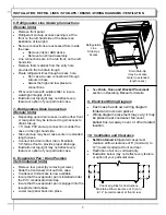
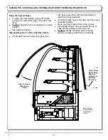
The Illustration below may not depict an exact
representation of your particular unit.
Rear Grille
Compressor Pan
Shipment Screw
(one at each side)
•
The toll-free number is listed in the Technical
Service section of this manual.
•
See Temperature Controller section in this
manual.
NOTE: Spirit-filled thermometers located in the
refrigerated compartment are for monitoring warm-
est air temperature in accordance with NSF Std. 7
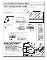
Evaporator Pan Access / Removal
•
Turn off main power; allow evaporator pan to
cool.
•
Lift Rear Grille up and off (no tools required).
•
WARNING! Evaporator Pan May Be Hot!
Check temperature of pan prior to handling.
•
Withdraw evaporator pan from the right side
behind electrical box.
•
Unplug evaporator pan from the electric outlet.
•
Empty evaporator pan contents into suitable
container. Replace rear panel when completed.
Refrigeration Package Access
Note: Servicing to be accomplished by licensed
electrical / refrigeration contractor.
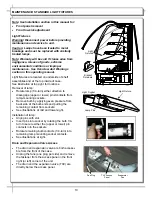
Air Filter
•
Magnetic strips attached to the filter adhere the
filter to the rear grille.
•
Clean the nylon mesh filter by rinsing thoroughly
with water against the air flow direction.
•
Mild detergent removes smoke & grease stains.
•
See illustration at top-right.
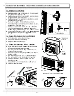
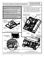
Pull Out Refrigeration Package
•
Remove the rear grille. Grille may be slid upward
and out or removal of two screws may be required.
•
Note: At initial slide-out, it may be necessary to
remove Compressor Pan Shipment Screws (see
illustration at right for location).
•
Refrigerant lines are flexible to facilitate rear access
maintenance.
•
Plastic glides are mounted at base to assist in sliding
the condenser out for access.
•
Service connections are at the left of compressor.
•
Slide condenser unit out 12 to 18 inches to access
high pressure service connection.
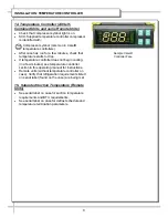
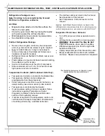
Temperature Controller (Self-Contained Units Only)
•
Temperature Controller is located in the Ballast Box.
•
Temperature / Defrost control settings are
programmable from these locations.
•
Case Temperature Set Point is set at the factory, as
determined by case size & sensor probe location.
•
Temperature is controlled by thermostat.
•
If a temperature setting change is required, follow
instructions
regarding
Temperature Control
Programming Steps in the technical information
section of this operating manual.
•
If service is required to the temperature control unit,
call Structural Concepts Corporation. Maintenance
should be performed by a certified technician.


