BULB INSTALLATION
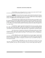
OBSERVE ALL SAFETY PROCEDURES when working around the xenon bulb. Open the
lamphouse access door by removing the tamperproof screws using the special screwdriver supplied. The igniter
lead and contact clamp are tied off for shipping. Free the clamp and slide it over the rear bulb support collet.
THE BULB SUPPORT YOKE in front of the reflector has three horizontal positioning holes
to permit setting the height of the yoke. The Gladiator II uses only the upper two holes. The spotlight is shipped
set up for use with the Hanovia XH2500HS bulb normally supplied with the unit, and the spring pin is through
the top hole. Because of a different end cap dimension, the bulb yoke must be raised and the pin installed in the
center hole if an Osram XBO2500W/HS bulb is used. The yoke may be repositioned by loosening the 8-32 set
screw in the support post. Tighten the set screw after setting the yoke position.
REMOVE THE PLASTIC PROTECTIVE COVER from the xenon bulb only if necessary.
Handle the bulb by the metal end caps only. Insert the bulb into the lamphouse, passing the anode (+) end cap
through the center hole of the reflector. Take care not to bump or scratch the surface of the reflector.
INSERT THE ANODE (+) PIN into the rear support collet and contact clamp. Rest the
cathode (-) end cap in the front bulb support yoke. Seat the anode (+) pin into the rear support collet as far as
possible for correct focus travel. Securely tighten the socket head clamping screw in the anode contact.
REST THE CATHODE END CAP in the “V” of the bulb yoke. Install the cathode contact
clamp over the cathode (-) pin. Firmly tighten the socket head clamping screw for a secure electrical contact.
Dress the negative DC lead attached to the contact clamp directly in front of the bulb support yoke to minimize
the projected shadow.
RECORD the bulb serial number, date, and lamphouse hours on the Xenon Bulb Record on the
inside back cover of this manual. This information will be needed in the event of a bulb warranty adjustment.
IT IS RECOMMENDED to use the above-mentioned lamphouse cables when installing the
xenon bulb. Anode leads supplied with bulbs are generally removable. If it is necessary to use the bulb anode
lead, remove the lamphouse igniter lead, and use the clamp to secure the bulb to the support collet. Attach the
bulb lead terminal to the igniter post; insulate the lead well and dress the lead away from grounded lamphouse
components.
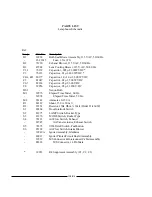
Rear Support Collet 39952
Rear Clamp
39194
Xenon Bulb, Type 2500HS
Cathode Contact
Clamp 39953
Front Bulb Support
Yoke 39975
Screw 00687
Clamping Screw 01532
XG2/007
Clamping Screw 01532
Содержание XENON GLADIATOR II
Страница 2: ......
Страница 27: ...1 2 3 4 5 6 7 8 9 10 11 12 13 FIGURE 1 XG2 025 ...
Страница 29: ...1 2 3 4 5 6 7 8 9 10 11 12 13 14 15 16 17 18 19 FIGURE 2 XG2 027 ...
Страница 32: ...1 2 3 4 5 6 7 8 9 10 11 12 13 FIGURE 3 XG2 030 ...
Страница 34: ...1 2 3 4 5 6 7 8 9 10 11 12 13 14 15 FIGURE 4 XG2 032 ...
Страница 36: ...1 2 3 4 5 6 7 8 9 10 FIGURE 5 IGNITER ASSEMBLY XG2 034 ...
Страница 39: ...FIGURE 6 XG2 037 ...
Страница 41: ...FIGURE 7 XG2 039 ...
Страница 43: ...FIGURE 8 XG2 041 ...
Страница 46: ...58 59 FIGURE 9 Item 58 Bracket mounts to back surface of Item 31 XG2 044 ...
Страница 50: ...FIGURE 10 47 XG2 048 ...
Страница 53: ......
Страница 54: ......


