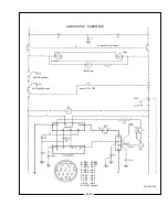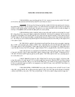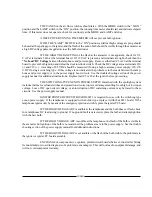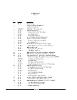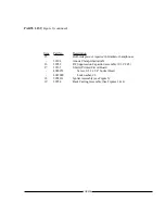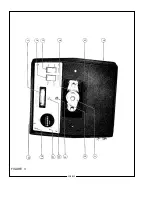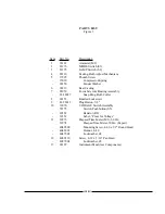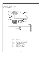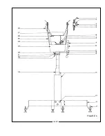
XENON GLADIATOR II TROUBLESHOOTING
Bulb fails to ignite.
1.
MODE switch S3 set to “AUTO.” Place in “MAN.” position when not employing automated or remote
lamphouse operation.
2.
AC power not on to lamphouse. Turn switching power supply 30 A. circuit breaker ON. If 115 V.AC
not read at 2 & 4, see power supply manual.
3.
Door interlock switch (S1) open. Close and secure lamphouse door.
4.
Faulty interlock switch(s). Check for 115 V.AC at 9 & 12; replace switch(s) if defective.
5.
Air vane switches not closing. Check for unobstructed operation; clean if required. Check continuity
between “NO” and “COM;” replace if defective.
6.
Faulty S2 “ON-OFF” switch. Check for voltage at 3 & 5; check for loose terminals or wiring. Replace
if defective.
7.
Blower fuse F1 blown. Replace as required (1.5 A. Std.).
8.
Low AC source voltage actuating “brownout” protection circuit in xenon power supply.
Bulb fails to ignite; ping audible, bulb flash visible.
1.
Inadequate DC output from xenon power supply. Set power supply output to correct range required for
bulb wattage (90 A. nominal for 2500 watt).
2.
If bulb flash is visible but faint, check for defective HV capacitor(s) in igniter. Replace if defective.
3.
Faulty or expired xenon bulb. Replace as required.
Bulb fails to ignite; ping audible, no bulb flash.
1.
Faulty xenon bulb. Check for cracked electrodes or darkened envelope. Replace if defective.
2.
Ignition pulse shorting to ground. Inspect DC leads for burned insulation; dress leads away from
grounded metal components.
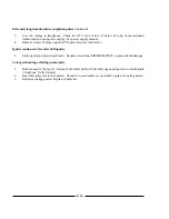
No high voltage ping audible; MODE switch in “MAN.” and LAMP switch in “ON.”
1.
Loss of AC control voltage. Check xenon power supply for tripped circuit breaker or open thermal
switch. See power supply manual.
2.
Little or no DC “No Load” voltage. Measure DC “No Load” voltage at 10 & 15. See power supply
manual.
3.
Open fuse F1 (600 V.) on switching power supply. SEE POWER SUPPLY MANUAL. Allow (20)
minutes for capacitor discharge before replacing.
4.
Faulty igniter printed circuit board. If lamphouse ignites immediately when emergency ignition switch
is pressed, replace printed circuit board.
5.
Loose spark gap connections or terminals. Repair or replace as required.
7.
Faulty igniter. Check for 115 V.AC at 5 & 6; adequate DC “No Load” at 10 & 15. If present, and
igniter does not fire, replace igniter.
XG2/022
Содержание XENON GLADIATOR II
Страница 2: ......
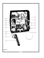
Страница 27: ...1 2 3 4 5 6 7 8 9 10 11 12 13 FIGURE 1 XG2 025 ...
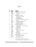
Страница 29: ...1 2 3 4 5 6 7 8 9 10 11 12 13 14 15 16 17 18 19 FIGURE 2 XG2 027 ...
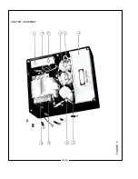
Страница 32: ...1 2 3 4 5 6 7 8 9 10 11 12 13 FIGURE 3 XG2 030 ...
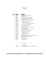
Страница 34: ...1 2 3 4 5 6 7 8 9 10 11 12 13 14 15 FIGURE 4 XG2 032 ...
Страница 36: ...1 2 3 4 5 6 7 8 9 10 FIGURE 5 IGNITER ASSEMBLY XG2 034 ...
Страница 39: ...FIGURE 6 XG2 037 ...
Страница 41: ...FIGURE 7 XG2 039 ...
Страница 43: ...FIGURE 8 XG2 041 ...
Страница 46: ...58 59 FIGURE 9 Item 58 Bracket mounts to back surface of Item 31 XG2 044 ...
Страница 50: ...FIGURE 10 47 XG2 048 ...
Страница 53: ......
Страница 54: ......


