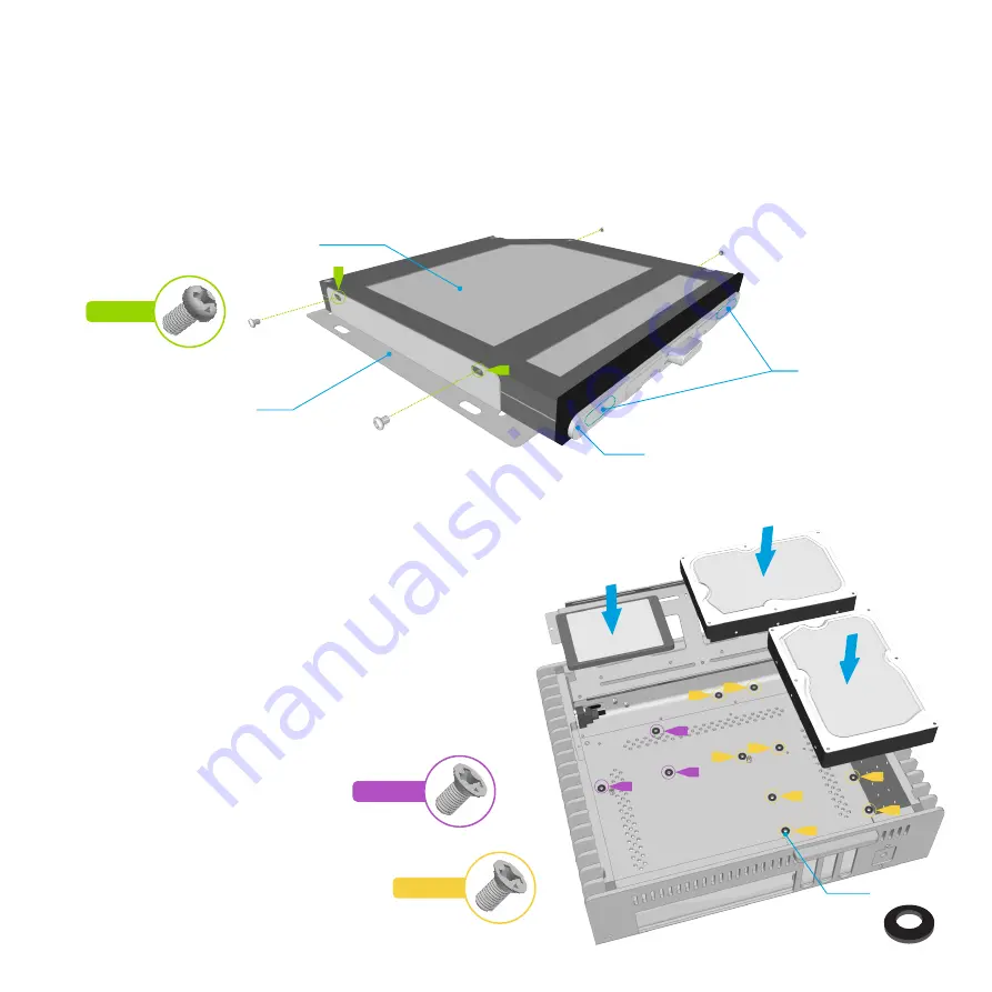
Optical Drive Preparation
The OPTICAL version of the FC9, includes a drive mounting bracket which must be fitted to the drive prior to installing it onto the drive tray.
Secure the optical drive to the drive bracket using the 4 x 2mm screws supplied. The drive should be pushed as far forward as possible without activating the eject
button before tightening the screws. If the screws meet any resistance (from internal components of the optical drive), do NOT tighten that screw any further, it
could damage the mechanism. Once secured to the bracket, test the eject button can function correctly. Depending on the eject button position and height, a
rubber pad might need to be affixed between eject bar and drive eject button. The pads can either be applied directly to the drives eject button, or to the opposite
side of the eject button, or both sides, whichever gives the best result.
Slimline Slot Loading Optical Drive
Optical Drive Mounting Bracket
Optional Rubber
Pad Locations
Bottom Panel Drive Options
If you are using a Mini-ITX motherboard, there is also room to fit hard
drives to the bottom panel of the case. Drives are secured in place
through the pre-drilled holes in the bottom panel in the locations show.
Screws should be attached through the bottom of the case and into the
drive. Optional rubber pads can be used to raise the drive off the bottom
panel, reducing vibration and improving airflow.
These drive locations should be used as a secondary option and only if
there is no more room on the drive tray. Fitting drives to the bottom panel
can reduce airflow as the lower vents are blocked, and this should be
taken into account if using high TDP components.
12
PH-M2x2
CS-M3x8
CS-6#32
A
A
A
A
B
B
B
B
C
C
C
A
C
B
Eject Bar
Rubber Pads
Содержание FC9A
Страница 1: ......
Страница 16: ...Designed in Europe Made in China Copyright 2014 Streacom All Rights Reserved ...


