Chapter 2. Installation and Operation of the SWXTL-BA SBB Tape Drive
Order Number: EK–SM1TB–UG. E01
2–3
Table 2–1 SWXTL-BA Tape Drive SCSI ID Switch Settings
Address
SW-1
SW-2
SW-3
SW-4
SW-5
SW-6
0
Off
Off
Off
Off
Off
Off
1
On
Off
Off
Off
Off
Off
2
Off
On
Off
Off
Off
Off
3
On
On
Off
Off
Off
Off
4
Off
Off
On
Off
Off
Off
5
On
Off
On
Off
Off
Off
6
Off
On
On
Off
Off
Off
7*
On
On
On
Off
Off
Off
Automatic
†
Off
Off
Off
On
On
On
* Normally reserved for host.
† Sets device address to storage subsystem slot number.
________________________________________________________________________________________________________________________
2.4
Installing the SWXTL-BA SBB Tape Drive Into a StorageWorks Expansion
Storage Subsystem
CAUTION
Refer to the applicable documentation for your host computer
and/or your specific operating system before installing the drive.
This installation procedure assumes that you have already in-
stalled and appropriately cabled the StorageWorks Storage Ex-
pansion Pedestal and have checked out that subsystem as appli-
cable, so that it is ready to receive this SBB unit.
You install the SWXTL-BA SBB tape drive in a storage subsystem by inserting the drive so
that the connector on the lower portion of the rear surface fits into any available SCSI device
storage slot. This means any of slots 2 through 6; the three-slot span of this SBB device
means that you cannot use slot 0 or 1, which are covered if you select slot 2, and slot 7 is
reserved for the pedestal power supply.
The drive can be installed using the hot-swap method where the drive is installed with the
host system powered on and operating, or with the host system powered off. Before using the
hot-swap method, consult your system administrator to ensure that your operating system
supports this type of installation.
To install the tape drive:
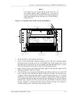
1. Open the door on the front bezel of the StorageWorks Expansion Storage Pedestal sub-
system (refer to Figure 2–2) and remove the bezel by pressing down on the plastic
locking tabs at the bottom inside surface of the bezel (just in front of the power supply)
and then pulling the bottom of the bezel forward, after which you can simply lift the
entire bezel assembly free.
2. Remove the filler panel (or any previously mounted SBB) from the desired three adjacent
device slots in the storage subsystem by squeezing the locking handles at the ends of
each respective panel (or SBB) and removing the panel (or SBB).


