26
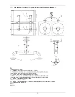
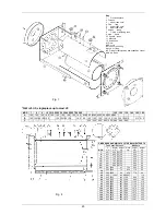
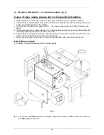
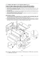
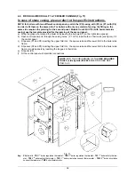
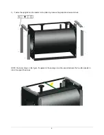
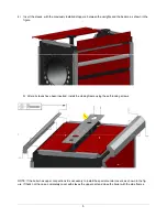
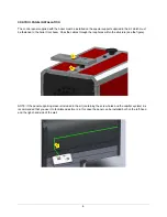
4.4 REX DUAL/REX DUAL F 14-70 BOILER CASINGS (Fig. 11)
In case of stave casing, please refer to the specific instructions.
NOTE: for boilers with two different control panels, switch the (P2) casing with (P3) or (P1) with (P4)
in order to fit them on the same side. For boilers with only one model of casing, the fitting on the
same side requires the piercing for the second panel. Models from 80 till 170 (with horizontal side
casing) use the template provided for the piercing of the second panel.
a) Wrap the glass wool around the boiler body leaving the bulb well (P) on the right side exposed.
b) Open control panel and, through the casing holes (P1 or P2) insert bulbs in their wells (see figure). Fit
the control panel.
c) Fit panels (P1 and P4) inserting the upper fold into the square tube and the lower fold to the boiler side
frame.
d) Fit panels (P2 and P3) inserting the upper fold into the square tube and the lower fold to the boiler side
frame; join side panels by inserting the tongues in their slots.
e) Fit panel (P5).
f) Fit the control panel with electrical connections
Fig. 11
Key: P
Bulb wells -
TR1
1
st
boiler regulation thermostat -
TR2
2
nd
boiler regulation thermostat -
TS1
1
st
boiler safety thermo-
stat -
TS2
2
nd
boiler safety thermostat –
TM1
1
st
boiler circulation consent thermometer -
TM2
2
nd
boiler circulation
consent thermometer -
TMC
boiler thermometer.
NOTE
: FOR THE POSITIONING OF THE
REX DUAL/REX
DUAL F (side by side) 80-260
BOILER’S BULBS SEE
PAR. 3.2.3.
Содержание REX F
Страница 1: ...TECHNICAL MANUAL REX REX F REX K REX K F REX DUAL REX DUAL F PRESSURISED STEEL BOILERS...
Страница 2: ......
Страница 18: ...18 1 2 6 3 4 5 9...
Страница 30: ......
Страница 32: ...ASSEMBLY INSTRUCTIONS STAVES LINING...
Страница 33: ......

