22
4 ASSEMBLY
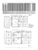
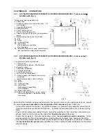
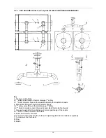
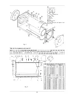
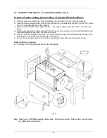
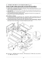
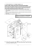
4.1 REX K/REX K F ASSEMBLY (Fig. 7-8)
Ensure that installation premises floor is even and perfectly horizontal.
For perfect welding, use acid or rutile cored electrodes (check codes AWS E6020 or AWS E6013 or E44LA3
or E44LC3).
a) Put the boiler rear plate (1) on the floor with the hinges pointing down and ensure that it is perfectly lev-
elled (mark the middle of the plate sides in order to position correctly the furnace and the tube nest.
b) Position the furnace (2) on the internal edge of the front plate (1) keeping the l ongitudinal welding of the
furnace in the lower part of the boiler.
Ensure that plate and furnace are perfectly perpendicular
when coupling them
.
c) Weld the furnace (2) onto the front plate (1) along the outer circumference.
d) Add the top tube nest part (3)* (the return stub which can be recognised by its flow trap (4) welded inside
the tube nest, must be close to the front tube plate).
For positioning, ensure that the flanged stub
hole axis is aligned with the sign previously marked on the plate middle
. For easy centering, check
height
A
between the tube nest edge and the plate edge. Spot-weld the middle only.
e) Position the lower tube nest (5)* in respect of height
B
and spot-weld it only in the lower middle part of
the rear plate (1).
f) Spot-weld the two tube nest parts (3)* and (5)*
g) Position the rear tube plate (6) and insert the tie rod or the stiffening stub (8) in the furnace.
h) Weld the rear tube plate (6) and the tie rod or stiffening stub (8), carefully avoiding any damage to the
four threaded rivets or screws which will be used to secure the smokebox.
i) Weld all the nest (3)* and (5)* onto the rear plate (1).
j) Now, smoke tubes (7) can be inserted and welded on the rear plate tube (6) keeping the boiler in upright
position or (but welding will be more difficult) horiz ontally; the choice will depend on the size of premises
and the equipment available to turn the boiler upside down.
Caution: smoke tuber (7) must protrude 3
mm from the front plate (1) and approx. 10 mm from the rear plate (6)
.
NB: the condensate groove for the F version (with extruded aluminium) must be positioned in the
lower section (see Fig. 8)
k) Spot-weld the drain (N4) and ensur e that it is perpendicular to the fr ont plate (1) and parallel to the tube
nest.
l) Position the boiler horizontally. For this reason, a lifting hook is supplied that can be conveniently welded
to the tube nest in order to simplify the boiler overturning. Remember not to have this hook protruding
form the casing.
m) Weld the two parts of the tube nest (3)* and (5)* longitudinally as well as the furnace inside (2) to the
front plate (1); you can simplify this operation by using rolls for rotating.
n) Weld both ½” couplings (N6) onto the tube nest (3)* after having ensured that the bulb sheaths inclina-
tion is correct to avoid that s heaths are not blocked by smoke tubes; remove sheaths when welding.
Weld the two flanged stubs (N1) and (N2) for flow and return, ensuring that flanges are perfectly horizon-
tal. Weld the instrument fitting (N3) and fittings (N5) if included in the supply.
o) Weld smoke tubes (7) onto the rear plate (1).
p) Ensure that plate shapes (1) and (6) have not been altered and weld on plate surface the side frames
(9).
q) Weld the square tubes (10) that support the casing and, if part of the supply, weld also the side ones
keeping height
C
.
r) Carry out the hydraulic test under pressure. FILL THE GUARANTEE WITH THE TEST DATE.
s) Install the manhole (11) and the smoke box (12).
t) Touch-up visible parts by using the paint supplied.
* NB: ref. 3-5, single piece up to mod. 25
Содержание REX F
Страница 1: ...TECHNICAL MANUAL REX REX F REX K REX K F REX DUAL REX DUAL F PRESSURISED STEEL BOILERS...
Страница 2: ......
Страница 18: ...18 1 2 6 3 4 5 9...
Страница 30: ......
Страница 32: ...ASSEMBLY INSTRUCTIONS STAVES LINING...
Страница 33: ......

