21
GB
Dimensioning
:KHQ GLPHQVLRQLQJ D ÀXH JDV
system, it’s necessary to perform
D FDOFXODWLRQ FKHFN RI WKH ÀXH JDV
system in order to verify if the
choosen
system
is
applicable.
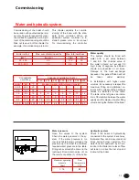
The following table shows an
H[DPSOH RI SRVVLEOH ÀXH JDV
system, including the maximum
possible length of the system.
This
example
only
give
an
indication of the possible length, but
LWFDQQRWEHXVHGIRURI¿FLDOÀXHJDV
OD\RXW FDOFXODWLRQ (DFK ÀXH JDV
system has to be calculated by an
authorized company.
7KH PD[LPXP QHJDWLYH ÀXH JDV
pressure, which doesn’t affect the
burner modulation ratio, is 30 Pa.
Higher negative pressure will lead
to limitation of the burner modulation
ratio.
7KHPD[LPXPKRUL]RQWDOÀXHJDVZD\
is 20 m. With horizontal ways longer
than 20 m, a faultless burner start in
cold condition can not be guaranteed.
Installation
Air/Flue gas system dimensioning
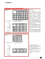
7ZLQSLSHÀXHJDV
system
0D[LPXPSHUPLVVLEOHOHQJWKRIÀXHJDVV\VWHPLQP
Length reduction factor
t
PHWHUVSHUHDFKEHQG
t
1,5 meters per each 45/43° bend
&RQFHQWULFÀXHJDV
system
0D[LPXPSHUPLVVLEOHOHQJWKRIÀXHJDVV\VWHPLQP
Length reduction factor
t
PHWHUVSHUHDFKEHQG
t
1 meter per each 45/43° bend
&DOFXODWLRQEDVH
7RWDOFRQQHFWLRQOHQJWKLQERLOHUURRPP
[EHQG
%RLOHUW\SH
7+/
7+/
7+/
VER
&DOFXODWLRQEDVH
7RWDOFRQQHFWLRQOHQJWKLQERLOHUURRPP
[EHQG
Maximum permissible height (h) of flue gas
system in m
%RLOHUW\SH
TH-L 65
6
61
7+/
7+/
7+/
TH-L 145
14
27
34
36
TH-L 50
6
61
&DOFXODWLRQEDVHURRIRUZDOOWHUPLQDO
7+/
7KH7+,6,21/ERLOHUPRGHOV
DQGFDQEHFRQQHFWHGWRD
WR
0XHOLQN *URO
&DOFXODWLRQEDVH
7RWDOFRQQHFWLRQOHQJWKLQERLOHUURRPP
[EHQG
Maximum permissible height (h) of flue gas
system in m
%RLOHUW\SH
TH-L 65
10
65
7+/
TH-L 100
20
34
42
44
7+/
7+/
&DOFXODWLRQEDVH
7RWDOFRQQHFWLRQOHQJWKLQERLOHUURRPP
[EHQG
%RLOHUW\SH
7+/
7+/
7+/
TH-L 50
10
65
&DOFXODWLRQEDVHURRIRUZDOOWHUPLQDO
7+/
7KH7+,6,21/ERLOHUPRGHOV
DQGFDQEHFRQQHFWHGWRD
WR
0XHOLQN *URO
Ø80
Ø100
Ø120
Ø125
Ø130
Lmax
[m]
Lmax
[m]
Lmax
[m]
Lmax
[m]
Lmax
[m]
24
40
13
40
22
33
26
40
40
17
24
40
40
12
17
40
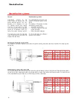
Equivalent length in m
Straight
pipe
Bend R=D
90°/87°
Bend R=D
45°/43°
Ø80
1
1.5
0.8
Ø100
1
1.8
0.9
Ø120
1
2
1
Ø125
1
2.2
1
Ø130
1
2.2
1
Ø 100 / 150
7
6
7
Equivalent length in m
Coaxial
pipe
Bend R=D
90°/87°
Bend R=D
45°/43°
Ø100/150
1.5
1
&RQFHQWULFÀXHJDVV\VWHP
7KH%RLOHUERLOHUPRGHOV
100 and 120 can be connected to a
FRQFHQWULFÀXHJDVV\VWHP
Via a parallel-to-concentric adap-
ter (optional) the boiler can be con-
QHFWHGWR
t
100/150 concentric system
6HHWDEOHIRUPD[SHUPLVVLEOHÀXH
lengths.
R40 45/50
R40 65
R40 85
R40 100
R40 120
R40 150
R40 45/50
R40 65
R40 85
R40 100
R40 120


