background image

18

on the right and left sides of the unit for free flow of air. Make
sure the machine is not pulling over 100° F (37° C) air from
other equipment in the area.

The water-cooled condenser is a tube and shell type. The
condenser needs a cool, clean supply of water to properly
cool the machine, inlet and discharge lines must be 3/8” I.D.
minimum.

The condenser and condenser filter require periodic clean-
ing. To clean, refer to the following procedures.

1.

Remove the Phillips head screw from the bottom of
the right side panel, and then slide the panels down
and out.

2.

To remove the condenser filter, grasp the top and
pull off. Visually inspect for dirt. If the filter is dirty,
shake or brush excess dirt off the filter and wash in
warm, soapy water. Once the filter is clean rinse
thoroughly in warm, clear water and shake dry,
taking care not to damage the filter in any way
(Figure 4-5).

3.

Visually inspect the condenser for dirt by shining
a light through the coil from the back (inside) of the
condenser.

4.

If the condenser is dirty, place a wet towel over the
outside of the condenser.

5.

Using compressed air or a CO2 tank, blow out the
dirt from the inside of the condenser. Most of the
dirt will cling to the wet towel.

NOTE

If the condenser is not kept clean, refrigeration effi-
ciency will be lost.

4.10

PREVENTATIVE MAINTENANCE

It is recommended that a preventative maintenance sched-
ule be followed to keep the machine clean and operating
properly. The following steps are suggested as a preventa-
tive maintenance guide.

The United States department of agriculture and the food
and drug administration require that lubricants used in
food zones be certified for this use. Use lubricants only in
accordance with the manufacturer’s instructions.

A.

Daily checks

Check for any unusual noise or condition and repair
immediately.

B.

Monthly checks

Check the condenser filter for dirt. (Refer to
section 4.9).

C.

Quarterly Checks

Check drive belts for wear and tighten belts if
necessary. (Refer to section 4.8)

4.11

EXTENDED STORAGE

Refer to the following steps for storage of the machine over
any long period of shutdown time:

A.

Clean thoroughly with warm detergent all parts
that come in contact with mix. Rinse in clear water
and dry all parts. Do not sanitize.

NOTE

Do not let cleaning solution stand in machine barrel
or mix pump during the shutdown period.

B.

Remove, disassemble, and clean the front door,
and auger shaft. Leave disassembled during the
shutdown period.

C.

Place the auger flights and auger support bushing
in a plastic bag with a moist paper towel. This will
prevent them from becoming brittle if exposed to
dry air over an extended period of time (over 30
days).

D.

For water-cooled machines that are left in unheated
buildings, or buildings subject to freezing, the
water must be shut off and disconnected.
Disconnect the water inlet fitting. The fitting is
located at the rear of the machine. Run the
compressor for 2 - 3 minutes to open water valve
(the front door must be attached for the compressor
to run). Blow out all water through water inlet. Drain
the water supply line coming to the machine.
Disconnect the water outlet fitting.

E.

Place the Main Freezer Power OFF/ON switch in
the OFF position.

F.

Disconnect the machine from the source of
electrical supply.

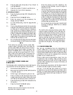
Figure 4-5 Condenser Filter Removal

Содержание E131-YG2

Страница 1: ...Model E131 YG2 F131 YG2 OPERATORS MANUAL Manual No 513649 Rev 1 ...

Страница 2: ......

Страница 3: ...s built prior to date of change DO NOT ATTEMPT to operate the machine until instructions and safety precautions in this manual are read completely and are thoroughly understood If problems develop or questions arise in connection with installation operation or servicing of the machine contact Stoelting Stoelting Foodservice Equipment 502 Highway 67 Kiel WI 53042 1600 U S A Main Tel 800 558 5807 Fa...

Страница 4: ...pecific safety information the following safety defini tions are provided to assist the reader The purpose of safety symbols is to attract your at tention to possible dangers The safety symbols and their explanations deserve your careful attention and understanding The safety warnings do not by themselves eliminate any danger The instructions or warnings they give are not substitutes for proper ac...

Страница 5: ...Transit 3 2 3 MachineInstallation 3 3 Initial Set Up and Operation 3 1 Operator sSafetyPrecautions 5 3 2 OperatingControlsandIndicators 5 3 3 ImportantInformationRegardingCleaningandSanitizing 7 3 4 Disassembly of Machine Parts 8 3 5 CleaningDisassembledParts 9 3 6 Sanitizing Machine Parts 9 3 7 CleaningtheMachine 9 3 8 Assembling the Machine 10 3 9 Sanitizing 10 3 10 InitialFreezeDownandOperation...

Страница 6: ...s and Modifying Settings 13 4 5 Readings 15 4 6 Adjustments 16 4 7 Other Settings 16 4 8 DriveBeltTensionAdjustment 17 4 9 CondenserCleaning 17 4 10 PreventativeMaintenance 18 4 11 ExtendedStorage 18 5 Troubleshooting 5 1 ErrorCodes 19 5 2 Troubleshooting 19 5 3 Troubleshooting Machine 21 6 Replacement Parts 6 1 Decals Lubrication 23 6 2 Auger Shaft and Faceplate Parts 24 ...

Страница 7: ... are designed to operate with almost any type of commercial softserveornon dairymixesavailable including icemilk ice cream yogurt and frozen dietary desserts Thismanualisdesignedtoassistqualifiedserviceperson nelandoperatorsintheinstallation operationandmainte nance of the Stoelting E131YG2 and F131YG2 gravity machine Figure 1 2 Specification 1 2 SPECIFICATIONS Figure 1 1 E131YG2 F131YG2 Machine ...

Страница 8: ... 40 1 4 102 2 cm 35 1 4 89 5 cm 450 lbs 204 1 kg 370 lbs 167 8 kg 1 Phase 208 230 VAC 60Hz approximately 12A Dimensions width height depth Weight Electrical running amps connection type International Option Compressor Drive Motor Air Flow Plumbing Fittings Hopper Volume Freezing Cylinder Volume Production Capacity 8 GPH 30 29 liters each Freezing Cylinder 11 5 GPH 43 53 liters both Freezing Cylind...

Страница 9: ...ation must be completed by a qualified electrician refrigeration specialist Incorrect installation may cause personal injury se vere damage to the machine and will void factory warranty Installation of the machine involves moving the machine close to its permanent location removing all crating setting in place assembling parts and cleaning A Uncrate the machine B Accuratelevelingisnecessaryforcorr...

Страница 10: ...4 ...

Страница 11: ...the machine until the main electrical power has been disconnected G Donotoperateunderunsafeoperatingconditions Neveroperatethemachineifunusualorexcessive noise or vibration occurs 3 2 OPERATING CONTROLS AND INDICATORS Before operating the machine it is required that the operatorknowthefunctionofeachoperatingcontrol Refer toFigure3 1forthelocationoftheoperatingcontrolsonthe machine For the informat...

Страница 12: ...ing cycle stops and the drivemotorwillstart ACLEANmessagewilldisplayonthe LCD screen along with a 5 minute countdown timer To exittheCLEANmode turntheFreezingCylinderOFF ON switch to the OFF position or press the CLEAN button again If the machine is left in CLEAN for more than 20 minutes anerrorcode E4 willbedisplayedonthedisplay panel Place the Freezing Cylinder OFF ON switch in the OFF position ...

Страница 13: ... of soil material milkstone Thorough cleaning pro cedures that involve milkstone removal are critical for operators of frozen dessert machines SANITIZING Kills bacteria Can be effective on clean surfaces only NOTE Using a SANITIZER on an unclean surface will not guarantee a clean and safe frozen dessert machine PROPER DAILY MAINTENANCE The Only Way to Assure Food Safety and Product Quality Proper ...

Страница 14: ... the solution That is why you can smell it Sanitizingsolutionsshouldnotbeallowedtofallbelow100 ppm chlorine New solutions should be mixed once old solutions become ineffective 3 4 DISASSEMBLY OF MACHINE PARTS Before using the machine for the first time complete machinedisassembly cleaningandsanitizingprocedures needtobefollowed Routinecleaningintervalsandproce dures must comply with the local and ...

Страница 15: ... the drip tray by pulling from the front panel Clean and replace the drip tray B DISASSEMBLYOFAUGER 1 Removethefrontaugersupportandbushing 2 Remove the auger assembly from the machine Pulltheaugeroutofthemachinebarrelslowly As the auger is being pulled out carefully remove each of the plastic flights with springs 3 Keeptherearoftheaugertippeduponceitisclear of the freezing cylinder to prevent the ...

Страница 16: ... of the support points straight up I Apply a thin layer of sanitary lubricant to the o ringsonthespigotbodyandinstallthespigotbody through the bottom of the front door K Apply a thin film of sanitary lubricant to the door seal o ring and fit it into the groove on the rear of the front door M Place the front door assembly on the mounting studsandthepushfrontdooragainstthemachine carefully N Securet...

Страница 17: ...ress the up arrow button once The display will read CutOut amps 8 Press the SET button A cursor will start blinking under the far right digit 9 Change the value to 8 0 Press the left arrow button to move the cursor Press the up arrow button to increase the digit When a digit reaches 9 pressing the up arrow button again will change the value to 0 10 After entering 8 0 press SET to save this value T...

Страница 18: ... PUSH TO FREEZE button NOTE After the drive motor starts there is a 3 second de lay before the compressor starts G When the product is at 75 consistency the display will read SERVE Open the spigot to dispense product H The machine dispenses product at a reasonable drawrate Ifthemachineisoverdrawn theresultis a soft product or a product that will not dispense at all If this occurs allow the machine...

Страница 19: ...on the control panel are disabled Follow the instructions below to lock the control panel A Press and hold the PUSH TO FREEZE button for at least 5 seconds B While still holding the PUSH TO FREEZE button press the CLEAN button once C Release both buttons An asterisk will appear on the bottom line of the display indicating that the control is in the lock out mode NOTE Repeat stepsA B and C to unloc...

Страница 20: ...14 Figure 4 2 IntelliTec Control Menu Settings ...

Страница 21: ... Cycles count This reading counts down the number of cycles in the current Serve Mode The starting value is dependantupontheCyclessettingontheIntelliTec control F and amps Suction line temperature on the freezing cylinder and drive motor amps are available on the same screen to assist with setup and troubleshooting Aux Temp F This reading provides the ambient temperature around the IntelliTec cont...

Страница 22: ...g this setting changes the temperature at which the freezing cycle starts ThisvaluealongwiththeCutOutvaluedetermines therangeoftemperatures or temperaturewindow of the product Decreasing the temperature decreases the temperature window and under normal use increases the amount of freezing cycles This creates a greater chance of product breakdownbystirringtheproductoften Increasing the Cut In T inc...

Страница 23: ... Off min If the temperature sensor in the hopper fails this setting determines the time between hopper refrigeration cycles This setting is only available on the left control Hpr On sec If the temperature sensor in the hopper fails this setting determines the length of the hopper refrigeration cycle This setting is only available on the left control 4 8 DRIVE BELT TENSION ADJUSTMENT To check belt ...

Страница 24: ... the food and drug administration require that lubricants used in food zones be certified for this use Use lubricants only in accordance with the manufacturer s instructions A Daily checks Checkforanyunusualnoiseorconditionandrepair immediately B Monthly checks Check the condenser filter for dirt Refer to section 4 9 C Quarterly Checks Check drive belts for wear and tighten belts if necessary Refe...

Страница 25: ...oductreachingconsistencyin Serve Mode or if the product does not reach proper temperaturein Sleep2Mode Thiserrorisgenerally causedbyverylowmixlevelsinthemachine smix container or from product breakdown Another commoncauseresultsfromarestrictionpreventing mixfromenteringthefreezingcylinder Checkthe mix in the hopper If the level mix is low add mix If there is a possibility that the mix has broken d...

Страница 26: ...fails Turn the Freezing Cylinder Off On switch Off and back On If the error persists contact your Authorized Stoelting Distributor for furtherassistance Error Code 11 Low Temperature TheLowTemperatureError E11 occurswhenthe temperature of the gas refrigerant at the barrel sensor falls below 20 F Although the machine will not shut down the active freezing cycle will immediately end This error usual...

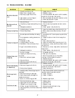
Страница 27: ... amps See Section 3 10 5 Remove mix clean sanitize and freeze down with fresh mix 6 Remove mix clean reassemble sanitize and freeze down 7 Check system See Section 5 Product does not dispense 1 No mix in hopper 2 Capacity of machine is being exceeded 3 Drive motor overload tripped 4 Drive belt failure 5 Freeze up Auger will not turn 1 Fill hopper with mix 2 Slow up on the draw rate 3 Wait for auto...

Страница 28: ...22 ...

Страница 29: ...al Stoelting Swirl Logo Drip Tray Support 1 324509 Decal Cleaning Instructions 1 324566 Decal Wired According To 1 324584 Decal Adequate Ventilation 3 1 324592 Decal Hold Ready 1 324593 Decal Power 1 324594 Decal Attention Heat Sensitive 1 324612 Decal Control 1 324686 Decal Danger Automatic Start 1 324803 Decal Domed Stoelting Logo Large Header Panel 1 324804 Decal Domed Stoelting Swirl Header Pa...

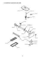
Страница 30: ...24 6 2 AUGER SHAFT AND FACEPLATE PARTS ...

Страница 31: ...r 5687 Plus 4 624678 5 O Ring Rear Seal Black 5 Pack 2 625133 O Ring Front Door Red 2 666786 Seal Rear Auger Black 2 694255 Spring Auger Flight 6 E131 8 F131 744260 SV Tray Drip 1 744273 Tray Drain Black Plastic 1 1159501 O Ring Bushing Kit 1177429 O Ring Spigot Extension Kit 2149243 01 Mix Inlet Assembly 3 16 Hole Standard Length 2A 2 2177072 Extension Spigot 1 5 2177073 Extension Spigot 2 5 2177...

Страница 32: ......

Страница 33: ...ese obligations remedies are subject to the conditions that Buyer a signs and returns to Stoelting upon installation the Start Up and Training Checklist for the affected equipment b gives Stoelting prompt written notice of any claimed breach of warranty within the applicable warranty period and c delivers the affected equipment to Stoelting or its designated service location in its original packag...

Страница 34: ...ted to hoses piping or electrical equipment e Labor and travel charges due to return trips or waiting if the Authorized Stoelting Provider is prevented from promptly starting service work upon arrival This exception includes labor charges incurred for limited access facilities including but not limited to government and military buildings and airports f Failure damage or repairs due to faulty inst...

Отзывы: