Tube Brace Assembly
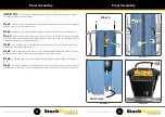
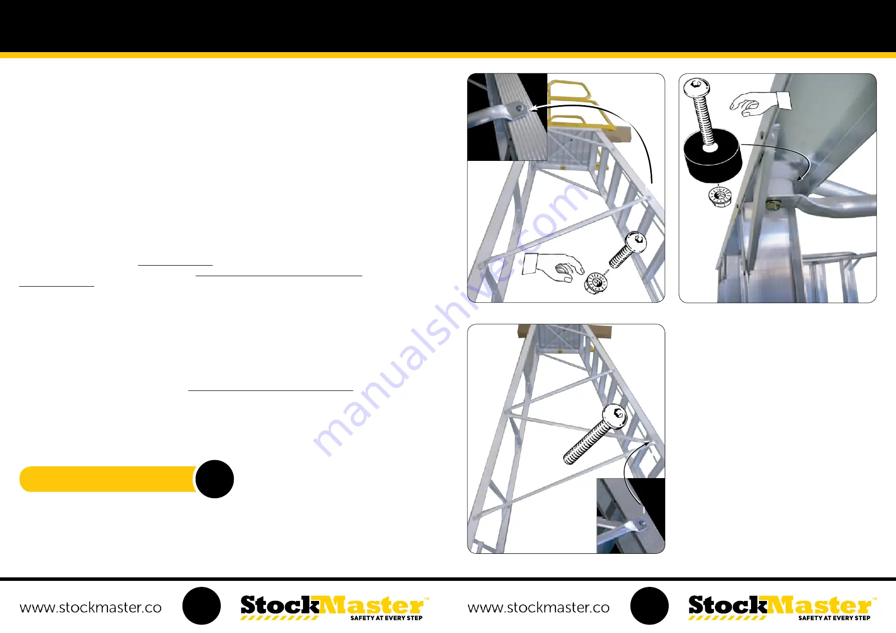
Illustration 1
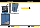
Illustration 2
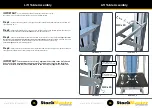
Illustration 3
A
B
B
A
M10 x 20
M10 x 20
B
B
Nylon Spacer
Nylon Spacer
C
C
D
D
M10 x 45
M10 x 45
IMPORTANT
:
To avoid assembly problems follow these instructions exactly. Work Safely - Do not stand the
frames upright when assembling. Place the frames in the positions as shown in the illustrations.
Instructions for sizes with 4 to 7 steps including the platform
:
There are no additional Tube Braces to be fitted to these sizes.
Proceed to Control Handle Assembly
Instructions for sizes with 8 to 11 steps including the platform:
See Step 1 only
Instructions for sizes with 12 to 14 steps including the platform:
See all Steps
Step 1
-
Fix one of the two shorter Tube Braces to the Front Frame at A using the M10 x 20 bolts and nuts supplied
with the Braces -
Finger tight only
.
For sizes 8 to 11 ONLY fix the other end of the Tube Brace at B on the Rear Frame then
turn the ladder over and repeat for the other side
. -
Note: Do not tighten the M10 bolts until advised.
For sizes 8 to 11 ONLY -
Proceed to Control Handle Assembly. (See illustration No. 1)
Step 2
- For sizes 12 to 14.
Fix the remaining end of the Shorter Tube Brace and one end of the Middle sized Tube
Brace to the Rear Frame at B using the M10 x 45 bolt, nut and spacer supplied. The Shorter Brace fixes to the outside
of the Frame. Fit the spacer over the bolt on the Inside of the Frame and fix the Middle sized Brace to the inside of the
Frame -
Finger tight only.
(See illustration No. 2)
Step 3
-
Fix the remaining end of the Middle sized Brace to the inside of the Front Frame and the Large Tube Brace
to the outside of the Frame at C -
Finger tight only
. Fix the remaining end of the Large Tube Brace at D -
Finger tight only.
Turn the ladder over and repeat for the other side. Note: Do not tighten the M10 bolts until advised.
(See illustration No. 3)
13
14
NEXT:
Proceed to Control Handle Assembly.
15


