


Configuration
Operating manual Axis switch POSISwitch® AX 5000
19
ID 441689.03
WE KEEP THINGS MOVING
7
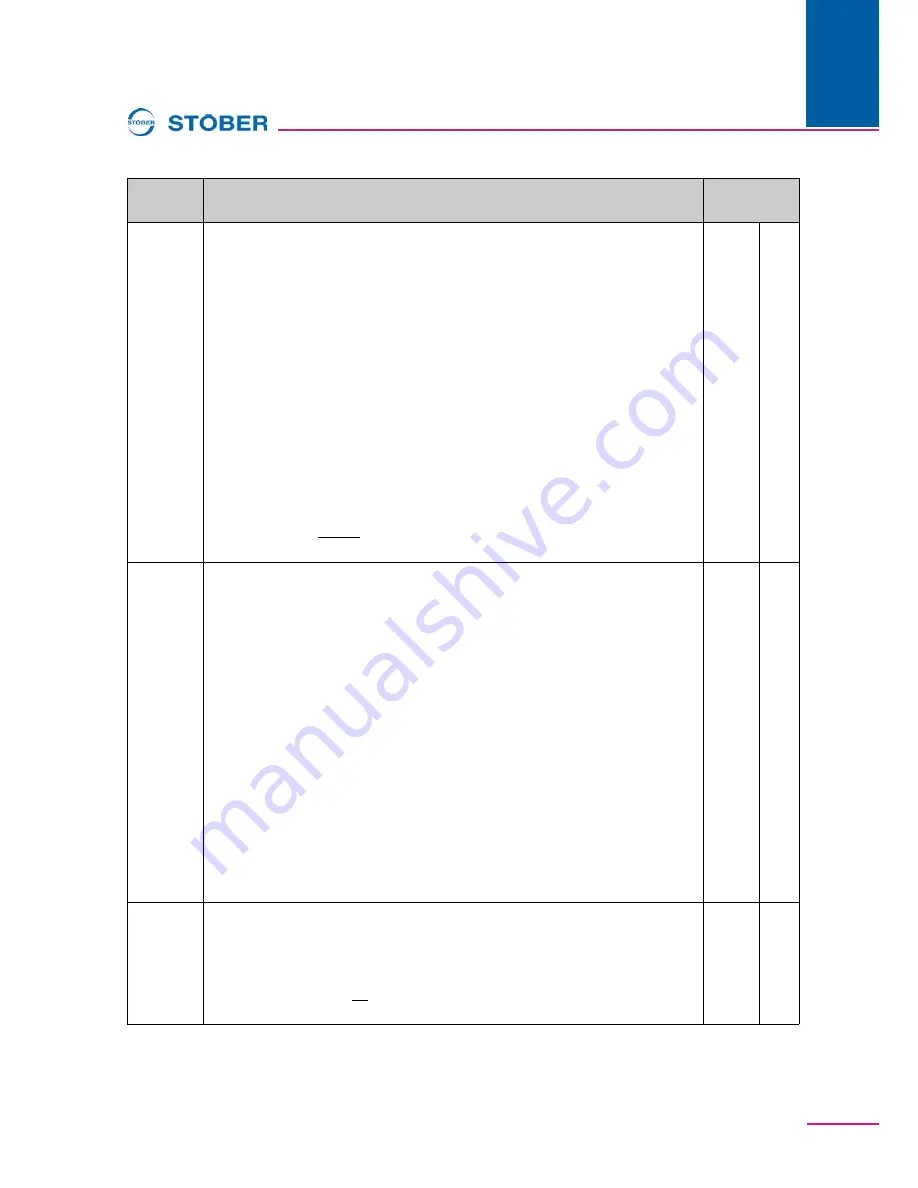
Par.
Description
Fieldbus-
address
A63
Global,
OFF
r=1, w=1
Axis selector 0 source:
There are 2 "axis selector 0/1" signals with which one
of the max. of 4 axes are selected in binary coding. The
A63
parameter specifies
where bit 0 for the axis selection is coming from. The possible selections "
0:Low
"
and "
1:High
" are the same as fixed values. With
A63 = 0:Low
, the bit is set
permanently to 0. With
A63 = 1:High
, it is permanently set to 1. With
A63 = 3:BE1
... 28:BE13-inverted
, the axis selection can be made via the selected binary
input. With
A63 = 2:Parameter
,
A180
, bit 3 is used as the signal source (global
parameter).
NOTE
•
Axis switchover is not possible unless the enable is off and
E48 device
control state
is not
5:fault
.
•
With the FDS 5000, the axes can only be used as parameter records for a
motor. The POSISwitch® AX 5000 option cannot be connected.
Value range: 0 ...
0: Low
... 28
Fieldbus: 1LSB=1; Type: U8; USS-Addr: 01 0F C0 00 hex
203Fh
0h
A64
Global,
OFF
r=1, w=1
Axis selector 1 source:
There are 2 "axis selector 0/1" signals with which one
of the max. of 4 axes are selected in binary coding. The
A64
parameter specifies
where bit 0 for the axis selection is coming from. The possible selections "
0:Low
"
and "
1:High
" are the same as fixed values. With
A64 = 0:Low
, the bit is set
permanently to 0. With
A64 = 1:High
, it is permanently set to 1. With
A64 = 3:BE1
... 28:BE13-inverted
, the axis selection can be made via the selected binary
input. With
A64 = 2:Parameter
,
A180
, bit 4 is used as the signal source (global
parameter).
NOTE
•
Axis switchover is not possible unless the enable is off and
E48 device
control state
is not
5:fault
.
•
With the FDS 5000, the axes can only be used as parameter records for a
motor. The POSISwitch® AX 5000 option cannot be connected.
Value range: 0 ... 0: Low ... 28
Fieldbus: 1LSB=1; Type: U8; USS-Addr: 01 10 00 00 hex
2040h
0h
F90
Global
r=2, w=3
Release time axis-switch:
Specifies the release time of the contactor used for
the axis switchover. This minimum time is waited before the inverter lets the next
contactor be applied.
Value range in ms:0 ...
20
... 32767
Fieldbus: 1LSB=1ms; Type: I16; USS-Adr: 06 16 80 00
hex
2A5Ah
0h


