ci-405
Page 4 of 4
REV 000
a
2002 STI-CO INDUSTRIES, INC., 11 Cobham Drive, Orchard Park, NY 14127-4187
Technical Support: E-mail: [email protected] Phone: 1-716-662-2680 Fax: 1-800-685-1122
Made in U.S.A.
TESTING AND VERIFICATION:
Installation testing, if required, must take place at the transmitter side of the feedline. This will ensure that the
cable connectors and cables have the proper continuity. Make sure all doors, hood, and trunk are closed.
Note:
Some vehicles are sensitive to VHF frequencies. STI-CO suggests that you isolate feedline and
check for unwanted interference with the ignition switch on.
1.
Reflective Power:
A measurement of reflective power using a wattmeter, you can expect up to 11%
reflected power. When results are greater than 11%, recheck grounding.
2.
SWR:
A measurement of SWR (standing wave ratio) will yield better than 2:1. If greater than 2:1,
recheck grounding.
3. Connect the feedline provided from the antenna base to a wattmeter. Connect from the wattmeter to the
transmit radio. Set the radio to a frequency that is closest to the center of the band of operation.
Measure the reflected power and note the value. Tune the mast by screwing it clockwise or counter
clockwise to lower the reflected power to it’s absolute minimum value. Select a frequency 5 MHz above
center and measure the reflected power. Note this value. Select a frequency 5 MHz below the center
frequency and record this number.
4. If the lower frequency number is higher than the upper frequency value, you must turn the antenna
counterclockwise until the two reflected power levels match.
5. If the upper frequency number is higher than the lower frequency value, you must turn the antenna
clockwise until the two reflected power levels match.
6. Once the to reflected power values are equal, the antenna is tuned, and you may proceed to the final
hook-up.
7. Connect the matching harness from the antenna base to the radio.
8. Installation is now complete.
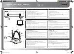
VHF BAND RADI
O
UHF BAND RADI
O
DUAL BAND COUPLER BOX
FEEDLI
NE
A
A
A
FEEDLI
NE
D
D