background image

Käyttöohje

User’s manual

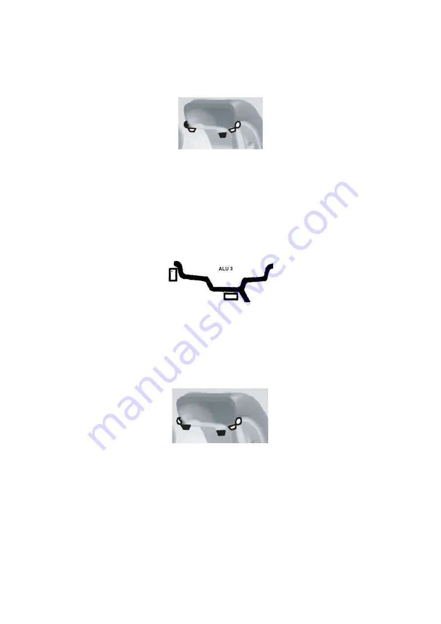
7.6. Inputting the rim’s data and balancing with the ALU-3 mode

Follow the instructions in chapter 7.2. to input the rim’s data and press the [MODE] key to enter ALU-1 balancing
mode (Fig 14).

Rotate the wheel by hand, and as the screen says ”RUN ---”, take your hands off the wheel and let it spin. As the 
screen says “STOP”, the wheel will stop and the screen will display the data of the wheel’s balance.

Rotate the wheel slowly. As the inner indicators all light up (10, Fig 3), attach the wheel, weight whose weight is 
displayed on the left screen, to the inner edge of the rim to twelve o’clock (Fig 15 left). Rotate the wheel slowly 
again. As the outer indicators all light up (11, Fig 3), attach the wheel weight, whose weight is displayed on the 
right screen, to the outer edge of the rim to twelve o’clock (Fig 15 right). Rotate the wheel slowly again by hand, 
and take your hands off the wheel as the display says “RUN ---”. When the display turns on again, the wheel will 
stop and the balancing will be complete.

7.7. Inputting the rim’s data and balancing with the ALU-S mode

The ALU balancing modes described before may not be suitable for all rim structures. The efficiency of the 
balancing may also suffer with some rims when using the other ALU modes. In cases like these, it is 
recommended to use the ALU-S balancing mode.

Press the [MODE] key until the ALU-S indicator lights up. The balancing mode is displayed in fig 16.

Move the measuring arm to the inner edge of the rim (aI position) as in fig 17, and measure the distance of the 
inner side of the rim and press [a+] or [a-] to input the value.

Move the measuring arm further (sE position), measure the value and press [b+] or [b-] to input it.

Measure the inner diameter of the rim (position aI) and press [d+] or [d-] to input the dI value. Measure the outer 
diameter (position aE), press [FINE] and [d+] or [d-] to input the dE value.

[38]

Fig 14

Fig 15

Fig 16

Содержание ST-1110

Страница 1: ...NOTUSKONE ST 1110 KÄYTTÖOHJE USER S MANUAL Lue tämä käyttöohje huolellisesti kokonaisuudessaan ennen koneen asennusta ja käyttöä Read the entire manual carefully and completely before installation or operation of the machine ...

Страница 2: ...äytön aloittaminen 10 7 2 Vanteen tietojen syöttäminen ja tasapainotus dynaamisessa tasapainotustilassa 10 7 3 Vanteen tietojen syöttäminen ja tasapainotus staattisessa ST tasapainotustilassa 11 7 4 Vanteen tietojen syöttäminen ja tasapainotus ALU 1 tasapainotustilassa 12 7 5 Vanteen tietojen syöttäminen ja tasapainotus ALU 2 tasapainotustilassa 12 7 6 Vanteen tietojen syöttäminen ja tasapainotus ...

Страница 3: ...osi 19 12 1 LED valojen ja indikaattorien tarkistus 19 12 2 Asentosensorin signaalin tarkistus 19 12 3 Painesensorin signaalin tarkistus 19 13 Ongelmanratkaisu 20 14 Huolto 21 14 1 Päivittäiset huoltotoimenpiteet 21 14 2 Ammattilaishuolto 21 15 Vianmääritystaulukko 22 16 Räjäytyskuvat 23 17 Varaosalista 24 3 ...

Страница 4: ...luun Ennen tasapainotusta varmista että rengas on tiukasti kiinni laipassa Koneen käyttäjän tulisi olla pukeutunut sopiviin vaatteisiin välttääkseen vaatekappaleiden roikkumisen Kukaan muu kuin koneen käyttäjä ei saa käynnistää konetta Konetta ei saa käyttää muuhun kuin sen suunniteltuun käyttötarkoitukseen 2 Tekniset tiedot ja toiminnot 2 1 Tekniset tiedot Renkaan maksimipaino 65 kg Virtalähde DC...

Страница 5: ...järjestelmä Koneen ohjausjärjestelmä koostuu LED näytöstä näppäimistöstä ja LSI piiristä esim uusi MCU prosessori Pyörimisnopeus ja paikannusjärjestelmä koostuu vaihteesta ja optisesta elektronisesta kytkimestä Kaksivaiheinen asynkroninen moottori ja sen ohjauspiiri Vaaka ja pystysuunnan paineanturit Renkaan suojakotelo 5 Kuva 1 MCU prosessori Virtalähde Koneen pääakseli Paikan ja pyörimisen mitta...

Страница 6: ... pihdit 1 kpl Kuusiokoloavain 1 kpl Mittavarsi 1 kpl Isopikalukitusmutteri 1 kpl Adapteri kartio 3 kpl Kalibrointipaino 100g 1 kpl 4 2 Koneen asentaminen Tasapainotuskone tulee asentaa tukevalle alustalle joka on yli 60 cm korkea Tasapainotuskoneen ympärillä tulee olla 50 cm tyhjää tilaa jotta koneen käyttö on helppoa Kiinnitä tasapainotuskone kolmella M8 ruuvilla 4 3 Akselin asentaminen Asenna va...

Страница 7: ...alkaisijan asetus 7 Näytä todellinen epätasapaino alle 5 grammaa toimintonäppäimet 1 gramma unssi 2 mm tuuma 3 itsekalibrointi 8 Uudelleenlaskenta 9 Tasapainotustilan valinta 10 Näytä epätasapainon sijainti ulkona 11 Näytä epätasapainon sijainti sisällä 12 Epätasapainon optimointi 13 Epätasapainon jakamistoiminto 14 Optimoinnin indikaattori 15 ALU S tilan indikaattori 16 Jakamisen indikaattori HUO...

Страница 8: ...non valintatoiminto FINE SET Paina painikkeita suorittaaksesi itsekalibroinnin FINE a a Paina painikkeita vaihtaaksesi yksikköä grammojen ja unssien välillä FINE MODE Paina painikkeita asettaaksesi koneen asetukset HUOM 1 Valittuasi yksiköksi grammat tai unssit valinta säilyy voimassa kun käynnistät koneen uudelleen 2 Valittusi vanteen leveyden ja halkaisijan yksiköksi millimetrit valinta ei säily...

Страница 9: ...inen asento Kuva 4 1 Positiivinen asento on yleensä käytössä Se on helppo kiinnittää ja se sopii monenlaisille perinteisille teräs ja alumiinivanteille B Negatiivinen asento Kuva 4 2 Negatiivista asentoa voidaan käyttää renkaan hyvän kiinnityksen saavuttamiseksi niilläkin vanteilla joiden ulkopuoli on vahingoittunut Käytä myös paksuilla teräsvanteilla Kiinnitä pyörä ja kartio akselille Varmista et...

Страница 10: ...tä vanteen leveys Tarkista leveys vanteesta tai mittaa vanteen leveys mitalla ja syötä mitattu arvo b näppäimillä b tai b Syötä vanteen halkaisija Tarkista halkaisija vanteesta tai mittaa vanteen leveys mitalla ja syötä mitattu arvo d näppäimillä d tai d Tasapainotus Pyöritä pyörää käsin ja kun näytössä lukee RUN ota kätesi pois pyörältä ja anna sen pyöriä Kun näytössä lukee STOP pyörä pysähtyy ja...

Страница 11: ...ä kunnes staattisen tasapainotustilan indikaattori syttyy päälle ja pääset staattiseen tasapainotukseen Pyöritä pyörää käsin ja kun näytössä lukee RUN ota kätesi pois pyörältä ja anna sen pyöriä Oikeassa näytössä näkyy teksti ST ja vasemmassa näytössä näkyy epätasapainon määrä Kuva 9 Kun rengas lopettaa pyörimisen pyöritä sitä hitaasti käsin kunnes sekä sisäpuolen 10 Kuva 3 että ulkopuolen 11 Kuva...

Страница 12: ... kun näytössä lukee RUN Kun näyttö syttyy taas päälle rengas pysähtyy ja tasapainotus on valmis 7 5 Vanteen tietojen syöttäminen ja tasapainotus ALU 2 tasapainotustilassa Seuraa kappaletta 7 2 syöttääksesi vanteen tiedot ja paina MODE näppäintä ja pääset ALU 2 tasapainotukseen Kuva 12 Pyöritä pyörää käsin ja kun näytössä lukee RUN ota kätesi pois pyörältä ja anna sen pyöriä Kun näytössä lukee STOP...

Страница 13: ...a 15 oikea Pyöritä pyörää taas hitaasti käsin ja ota kätesi pois pyörältä kun näytössä lukee RUN Kun näyttö syttyy taas päälle rengas pysähtyy ja tasapainotus on valmis 7 7 Vanteen tietojen syöttäminen ja tasapainotus ALU S tasapainotustilassa Yllä kuvatut ALU tasapainotustilat eivät välttämättä sovi kaikille vannerakenteille Lisäksi tasapainotustehokkuus saattaa muilla ALU toiminnoilla kärsiä joi...

Страница 14: ...sen näytön näyttämän lukeman painoinen rengaspaino vanteen sisäpuolelle aI asentoon kello kahteentoista Kuva 18 Pyöritä rengasta taas hitaasti Kun ulkopuolen indikaattorit syttyvät 11 Kuva 3 kiinnitä sopiva rengaspaino joka näkyy oikeanpuoleisessa näytössä vanteen ulkopuolelle aE asentoon kello kahteentoista Kuva 18 Pyöritä pyörää taas hitaasti käsin ja ota kätesi pois pyörältä kun näytössä lukee ...

Страница 15: ...soittaa suoraan ylöspäin Paina FUNC painiketta Pyöritä rengasta taas hitaasti ja löydä molemmat epätasapainokohdat indikaattorien avulla Kiinnitä kahteen samanpainoiseen osaan jaetun rengaspainon puolikas molempiin epätasapainokohtiin Pyöritä rengasta nopeasti suorittaaksesi tasapainotuksen Jos rengas on tasapainossa rengaspainojen jakaminen ja piilokiinnitys on onnistunut 7 9 Uudelleenlaskenta En...

Страница 16: ...n epätasapainon arvo on 40 grammaa ja optimointiprosentti on 85 on epätasapainon määrä optimoinnin jälkeen 6 grammaa 0 15 x 40 grammaa 6 grammaa Pyöritä rengasta hitaasti käsin ja kun molempien asentoindikaattorien ylimmät ja alimmat valot välähtävät Kuva 22 merkitse rengas taas liidulla Pyöritä rengasta taas käsin ja kun molempien asentoindikaattorien keskimmäiset valot vilkkuvat Kuva 23 merkitse...

Страница 17: ...Käyttöohje User s manual 17 ...

Страница 18: ...n ulkoreunalle Kuva 25 ja pyöritä rengasta manuaalisesti kunnes näyttö pimenee Ota kätesi renkaalta siirtyäksesi seuraavaan vaiheeseen tai paina SET lopettaaksesi Kun pyöritys loppuu myös kalibrointi on valmis Kuva 26 Irrota rengas koneesta Kone on nyt valmis käytettäväksi HUOM Kun suoritat itsekalibrointia syötettyjen vanteen tietojen täytyy olla oikeat ja 100 gramman kalibrointipainon täytyy oll...

Страница 19: ...eisiin sopivaksi Seuraa kappaleen 11 2 ohjeita ja paina a siirtyäksesi kirkkauden asetuksiin Kuva 29 Oikeanpuoleinen näyttö osoittaa kirkkaustason joita on kaikkiaan kahdeksan Taso 1 on himmein ja taso 8 kirkkain näytön kirkkaus Oletuksena näytön kirkkaus on tasolla 4 Paina b tai b muuttaaksesi kirkkaustasoa Paina painiketta a siirtyäksesi seuraavaan vaiheeseen 11 4 Mittayksikön muuttaminen Suurim...

Страница 20: ...ori pääakseli ja emolevy vikojen varalta Pyöritä akselia hitaasti jolloin kuvan 31 oikeanpuoleiset arvot muuttuvat Pyörittäessäsi akselia myötäpäivään arvo kasvaa ja vastapäivään pyörittäessäsi arvo pienenee Normaalit arvot ovat 0 ja 63 välillä Paina a siirtyäksesi painesensorin signaalin tarkistukseen tai paina SET painiketta poistuaksesi diagnoosista 12 3 Painesensorin signaalin tarkistus Tällä ...

Страница 21: ...nuksesta koneeseen tai siitä ettei konetta ole kiinnitetty lattiaan kunnolla Kiinnitä kone lattiaan ankkuripulteilla Vinkki Tasapainotuskoneen tarkkuuden tarkistaminen Syötä vanteen oikeat tiedot a b d arvot ja suorita itsekalibrointi Suorita tasapainomittaus ja ota ylös koneen antamat arvot Kiinnitä tämän jälkeen 100 gramman kalibrointipaino vanteen ulkoreunaan kohtaan jossa ulkopuolen epätasapai...

Страница 22: ...minnassa ilmenee selviä toimintavirheitä jotka eivät korjaannu itsekalibroinnilla täytyy ottaa yhteyttä ammattihuoltoon Voima antureiden säätäminen ja vaihto kuuluu ammattilaisille ja se tulee suorittaa seuraavasti 1 Irrota No 1 2 3 4 5 mutterit 2 Irrota anturi ja mutteri 3 Vaihda No 6 7 anturit 4 Asenna anturit ja mutterit Kuvan 33 mukaisesti ole tarkka antureiden suunnasta 5 Kiristä mutteri No 1...

Страница 23: ...Pääakseli pyörii väärään suuntaan 1 Paikka anturin häiriö 2 Tietokoneen emolevyn häiriö 1 Vaihda paikka anturi 2 Vaihda tietokoneen emolevy Err 5 Sensorin virtapiiri ei toimi 1 Häiriö virtalähteessä 2 Tietokoneen emolevyn häiriö 1 Vaihda virtalähde 2 Vaihda tietokoneen emolevy Err 6 Tietojen menetys 1 Epäonnistunut itsekalibrointi 2 Tietokoneen emolevyn häiriö 1 Toista itsekalibrointi 2 Vaihda tie...

Страница 24: ...Käyttöohje User s manual 16 Räjäytyskuvat 24 ...

Страница 25: ...Käyttöohje User s manual 25 ...

Страница 26: ...8 014 100251 0 Screw 5 9 PX 110 010200 0 Mounting base 1 29 s 100 000110 0 Complete Shaft 1 10 PX 110 010000 0 Chassis 1 30 PZ OOO 040110 0 Position Pick up Board 1 12 B 024 050101 1 Screw 1 31 PZ OOO 020110 0 Power Board 1 13 P 100 160200 0 Head 1 100 312 P 100 080000 0 Screw 1 14 P 822 160100 0 Handle 1 100 315 s 131 000010 0 Sensor Assembly 2 15 8 010 060161 0 Screw 1 100 317 P 100 070000 0 Scr...

Страница 27: ...cing with the dynamic balancing mode 7 3 Inputting the rim s data and balancing with the static ST balancing mode 7 4 Inputting the rim s data and balancing with the ALU 1 mode 7 5 Inputting the rim s data and balancing with the ALU 2 mode 7 6 Inputting the rim s data and balancing with the ALU 3 mode 7 7 Inputting the rim s data and balancing with the ALU S mode 7 8 Splitting and hiding the wheel...

Страница 28: ... Position sensor signal check 12 3 Pressure sensor signal check 13 Troubleshooting 14 Maintenance 14 1 Daily maintenance procedures 14 2 Professional maintenance 15 Troubleshooting table 16 Explosion diagram 17 Spare parts list 28 ...

Страница 29: ...ogy service The user should wear fitting clothes to avoid any hanging cloth articles Anyone other than the operator of the machine isn t allowed to turn it on Do not use the machine for anything else than its intended purpose 2 Technical data and functions 2 1 Technical data Maximum wheel weight 65 kg Power source DC12V 1A Rotating speed 120 r min Sequence length 8s Rim diameter 10 24 256 mm 610 m...

Страница 30: ...stem The control unit of the machine consists of the LED screen the keyboard and the LSI circuit for example the new MCU processor The system that detects the rotation speed and location consists of the gears and the optical electronical coupling The two step asynchronous motor and its control circuit Pressure sensors of the horizontal and vertical directions 30 MCU CPU Power supply Main shaft Rot...

Страница 31: ...ht pliers 1 pc Allen key 1 pc Rim width interpreter 1 pc Large quick locking nut 1 pc Adapter cone 3 pcs Calibrating weight 100 g 1 pc 4 2 Installing the machine The machine must be installed on a stable surface that is at least 60 cm high There should be 50 cm of free space around the machine to make it easier to use Install the machine with three M8 screws 4 3 Installing the shaft Install the ri...

Страница 32: ... 6 Buttons manual diameter setting 7 Show the true amount of imbalance under 5 grams function keys 1 gram ounce 2 mm inch 3 self calibration 8 Re calculate 9 Select balancing mode 10 Show the position of the outer imbalance 11 Show the position of the outer imbalance 12 Optimize the imbalance 13 Split the imbalance 14 Optimization indicator 15 ALU mode indicator 16 Split function indicator NOTE On...

Страница 33: ... SET Press these buttons to seolf calibrate FINE a a Press these buttons to toggle between grams and ounces FINE MODE Press these buttons to access machine settings NOTE 1 After choosing the unit as grams or ounces the selections stay the same after shutting down the machine 2 After choosing the unit of width and diameter as millimeters the selection will not stay the same after shutting down the ...

Страница 34: ...le of the rim There are two ways to attach the wheel the positive position A and the negative position B A Positive position Fig 4 1 The positive position is the most common one It is easy to use and it fits most traditional aluminum and steel rims B Negative position Fig 4 2 The negative position can be used with rims that have a deformed outer side Use it with thick steel rims also 6 3 Detaching...

Страница 35: ...rated in fig 5 7 2 Inputting the rim s data and balancing with the dynamic balancing mode When the machine is on it will begin the normal balancing mode as demonstrated below Fig 6 Input the rim s distance Move the measuring arm to the inner edge of the rim as in fig 6 measure the a value and press a or a to input the value Input the rim s width Check the width written on the rim or measure it wit...

Страница 36: ...utting the rim s data and balancing with the static ST balancing mode The static balancing mode is suitable for rims on which the wheel weights can only be clamped to the middle position like motorcycle rims Under static mode measure the diameter Fig 8 and input the d value with d or d keys a and b values can be anything Press MODE key to turn the static mode indicator on and to enter the static b...

Страница 37: ...y says RUN When the display turns on again the wheel will stop and the balancing will be complete 7 5 Inputting the rim s data and balancing with the ALU 2 mode Follow the instructions in chapter 7 2 to input the rim s data and press the MODE key to enter ALU 1 balancing mode Fig 12 Rotate the wheel by hand and as the screen says RUN take your hands off the wheel and let it spin As the screen says...

Страница 38: ...heel slowly again by hand and take your hands off the wheel as the display says RUN When the display turns on again the wheel will stop and the balancing will be complete 7 7 Inputting the rim s data and balancing with the ALU S mode The ALU balancing modes described before may not be suitable for all rim structures The efficiency of the balancing may also suffer with some rims when using the othe...

Страница 39: ...ayed on the left screen to the aI position on the inner edge of the rim to twelve o clock Fig 18 Rotate the wheel slowly again As the outer indicators all light up 11 Fig 3 attach the wheel weight whose weight is displayed on the right screen to the aE position on the outer edge of the rim to twelve o clock Fig 15 right Rotate the wheel slowly again by hand and take your hands off the wheel as the...

Страница 40: ...heel slowly until a spoke points directly up Press the FUNC key Rotate the wheel slowly again and find both positions of imbalance with the help of the indicators Attach half of the wheel weight that has been split in two equal pieces to both positions of imbalance Spin the wheel fast to balance it If the wheel is balanced the split and hide function has been successful 7 9 Recalculation Before ba...

Страница 41: ...which the display will look like fig 21 In fig 21 the left screen displays the optimization percentage If before optimization the imbalance value was 40 grams and the optimization percentage is 85 the imbalance value will be 6 grams after optimization 0 15 x 40 grams 6 grams Rotate the wheel slowly by hand and the upper and lower lights of both imbalance position indicators flash Fig 22 mark the t...

Страница 42: ... the machine Follow the instructions in chapter 7 2 to input the rim s data Press FINE SET keys Fig 24 and rotate the wheel manually until the display turns blank and move your hands away from the wheel If the display says REDUCE it means that the rotation speed is too high If the rotation speed is normal the display will say RIN When the display says STOP the wheel will stop rotating and the disp...

Страница 43: ...e next step 11 2 Keyboard sound effect settings This function can be used to toggle the keyboard sound effects on and off If the function is selected the machine will emit a beep every time a key is pressed If the function is off the machine can be used silently Follow the instructions in chapter 11 1 and press a to enter the interface shown in fig 18 If the right screen displays ON the sounds are...

Страница 44: ... SET MODE keys indicator lights and LEDs With this function you can detect which lights are damaged The check will complete and the screen will look like fig 27 Move on to the position sensor signal check or press SET to exit self diagnosis 12 2 Position sensor signal check This function can be used to check the position sensor main shaft and mother board for any faults Rotate the shaft slowly whi...

Страница 45: ... weight The original 100 gram calibrating weight must be kept safe for future use If the data changes between balances it isn t caused by the machine It can be caused by the wheel being badly installed on the machine or the machine not being properly installed to the floor Attach the machine to the floor with anchor bolts Hint Checking the accuracy of the wheel balancer Input the rim s correct dat...

Страница 46: ...tionality has any apparent errors that don t get fixed with self calibration it is necessary to contact the professional maintenance service Adjusting the power sensors and changing them is meant to be done by professionals as follows 1 Unscrew the nuts No 1 2 3 4 5 2 Detach the sensor and nut 3 Change the sensors No 6 7 4 Install the sensors and nuts as in Fig 33 be careful about the direction of...

Страница 47: ...to the wrong direction 1 Position sensor faulty 2 Computer board faulty 1 Change position sensor 2 Change computer board Err 5 Sensor signal transact circuit not working 1 Power supply faulty 2 Computer board faulty 1 Change power supply 2 Change computer board Err 6 Data loss 1 Incorrect self calibration 2 Computer board faulty 1 Repeat the self calibration 2 Change computer board Err 7 Self cali...

Страница 48: ...Käyttöohje User s manual 16 Explosion diagram 48 ...

Страница 49: ...Käyttöohje User s manual 49 ...

Страница 50: ...0 Plate 1 28 8 014 100251 0 Screw 5 9 PX 110 010200 0 Mounting base 1 29 s 100 000110 0 Complete Shaft 1 10 PX 110 010000 0 Chassis 1 30 PZ OOO 040110 0 Position Pick up Board 1 12 B 024 050101 1 Screw 1 31 PZ OOO 020110 0 Power Board 1 13 P 100 160200 0 Head 1 100 312 P 100 080000 0 Screw 1 14 P 822 160100 0 Handle 1 100 315 s 131 000010 0 Sensor Assembly 2 15 8 010 060161 0 Screw 1 100 317 P 100...

Отзывы:

Похожие инструкции для ST-1110