background image

07300800 rev. B 31-10-2014 

27 

 
standard leveller. For any optional applications, the control must 
be programmed by means of an optionally available display.  
For the available settings, refer to the manual of SSC and the SMC 
control box, that is available on request. 

Trouble shooting 

Caution:

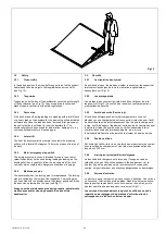
 always use the maintenance pins during all maintenance 

and repair work. 
 

The deck does not rise when the control button is pressed 
because the motor is not running. 

1.  Is the mains supply switched on? 
2.  Is the mains voltage present?  
3.  Check the safety circuit C-C and D-D (if used), see control 
 

current diagram Fig. G. 

4.  Check the electrical cables. 
 

The deck does not rise (not sufficiently) even though the 
motor is running. 

Check the oil level. 

Check whether the pump is building up pressure. This is 


indicated by the hydraulic hose of the main cylinder (Fig. E). 

3.  Check the main cylinder and lines for leakage. 
4.  Check the rotating direction of the electric motor. 
5.  Check that the pressure relief valve (Fig. D) is set correctly. 
6.  Check for mechanical damage. 
7.  Is there a load on the dockleveller? 
8.  Check the operation of the stop valve (Fig. D) (Y3). 
 

The lip of the dockleveller does not extend/retract properly 
even though the motor is running. 

1.  Check the oil level. 
2.  Check whether the pump is building up pressure. This is 
 

indicated by the hydraulic hose of the lip cylinder (Fig. F). 

3.  Check the lip cylinder and lines for leakage. 
4.  Check the electrical connection of the lip valves (Fig. G). 
5.  Check for mechanical damage. 
6.  Check that the pressure relief valve (Fig. D) is set correctly. 
7.  Check the throttle for blockage. 
8.  Check the wiring of the reed contact (lip-in switch, Fig. F). 
 

The deck of the dockleveller is not lowering or lowering 
insufficiently. 

1.  The safety valve (Fig. E.4) in the main cylinder is closed or 
 

the pressure switch (Fig. D) is activated.

 Briefly press the 


button with the arrow pointing up.


2.  Check the operation of the stop valve (Fig. D) (Y3). 
3.  Check for mechanical damage or obstruction. 
4.  Check the adjustable restriction (Fig. D) in the shuttle valve. 
 

AUTO-RETURN with push button is not operating properly. 

Pump motor keeps running, dockleveller is in lifted position. 
1.  Check the wiring of the reed contact (lip-in switch, Fig. F). 
2.  In this case the dockleveller can eventually also manually be 
 

moved in parked position. Switch off and on the main switch 


and move the dockleveller with the normal controls to parked 


position. 

 
Consult your dealer/supplier for the correct settings, repairs and 
maintenance. 
Incorrect adjustments, repairs and maintenance can endanger 
people and goods etc. 


niveleur standard. Pour toutes les applications en option, la 
commande doit être programmé au moyen d'un écran en option. 
Pour les réglages, voir le manuel du boîtier de commande SSC et 
SMC, qui est disponible sur demande. 

Diagnostic des pannes 

Attention:

 Lors de travaux d'entretien ou de réparations, il faut 

toujours se servir des verrous 

d’entretien. 


Le niveleur ne se lève pas lors de la commande du bouton 
parce que le moteur ne fonctionne pas. 

1.  Le circuit principal est-il branché? 
2.  La tension du réseau est-elle disponible? 
3.  Vérifiez les connexions de sécurité C-C et D-D avec la porte 
 

(si utilisé), voir schéma électrique (Fig. G)

4.  Vérifiez le câblage électrique. 
 

Le niveleur ne se lève pas (suffisamment), bien que le moteur 
fonctionne. 

1.  Vérifiez le niveau de l'huile. 
2.  Vérifiez si la pompe produit une pression. Ceci se 
 

remarque au tuyau du cylindre hydraulique principal (Fig. E). 

3.  Vérifiez si le cylindre principal et les conduites ont des fuites. 
4.  Vérifiez le sens de rotation du moteur électrique. 
5.  Vérifiez que le limiteur de pression (Fig. D) est correctement 
 

réglé. 

6. 

Vérifiez l’absence de dégâts mécaniques. 

7.  Y a-t-il une charge sur le tablier? 
8.  Vérifiez le fonctionnement de la valve d'arrêt (Fig. D) (Y3). 
 

La lèvre du niveleur de quai ne sort/rentre pas (suffisamment), 
bien que le moteur fonctionne. 

1.  Vérifiez le niveau de l'huile. 
2.  Vérifiez si la pompe produit une pression. Ceci se 
 

remarque au tuyau du cylindre hydraulique de la lèvre (Fig. F). 

3.  Vérifiez si le cylindre de la lèvre et les conduites ont des fuites. 
4.  Vérifiez la connexion électrique des valves du cylindre de la 
 

lèvre (Fig. G). 

5. 

Vérifiez l’absence de dégâts mécaniques. 

6.  Vérifiez que le limiteur de pression est (Fig. D) correctement 
 

réglé. 

7.  Vérifiez que l'étranglement n'est pas bloqué. 
8.  Vérifiez le câblage du contact à lames souples (interrupteur 
 

lèvre rétracté, Fig. F). 


Le tablier 

du niveleur de quai ne s’abaisse pas ou ne 

s’abaisse suffisamment. 

1.  La valve de sécurité (Fig. E.4) du cylindre du tablier est 
 

f

ermée ou l’interrupteur à pression (Fig. D) est actionné. 


Pressez brièvement le bouton avec la flèche dirigée en haut. 

2.  Vérifiez le fonctionnement de la valve d'arrêt (Fig. D) (Y3). 
3.  Vérifiez l'absence de dégâts mécaniques et d'obstructions. 
4.  Vérifiez que l'étranglement réglable (Fig. D) n'est pas bloqué. 
 

AUTO-RETOUR par bouton-poussoir ne fonctionne pas bien. 

Pompe moteur continue à fonctionner, niveleur continue à monter. 
1.  Vérifiez le câblage du contact à lames souples (interrupteur 
 

lèvre rétracté, Fig. F). 

2.  Dans ce cas, le niveleur de quai peut éventuellement aussi 
 

être mis en position de repos manuellement. Mettez 


l'interrupteur principal hors et sur et 

manœuvrez le niveleur de 


quai avec les commandes normales dans la position de repos. 

 
Pour effectuer les bons réglages, réparations et entretiens, 
consultez votre détaillant/fournisseur. 
Des réglages, réparations et entretiens inappropriés peuvent 
mettre les personnes, les marchandises, etc. en danger. 

Содержание XPH 2020

Страница 1: ...Handleiding XPH laadbrug Anleitung XPH Überladebrücke Manual XPH dockleveller Mode d emploi niveleur de quai XPH 07300800 rev B 18 11 2014 ...

Страница 2: ......
Страница 3: ...edieningskasten voldoen aan de Laagspanningsrichtlijn 2006 95 EG en de EMC richtlijn 2004 108 EG EG KONFORMITÄTSERKLÄRUNG FÜR MASCHINEN EG Richtlinie 2006 42 EG Anlage II unter A Fabrikant Stertil B V Westkern 3 9288 CA KOOTSTERTILLE NL Der Unterzeichnete U G Bijlsma Geschäftsführer der zu diesem Zwecke von der Firma Stertil B V bevollmächtigt wurde erklärt hiermit daß die Überladebrücken Marke ST...

Страница 4: ...tive 2004 108 EC ATTESTATION DE CONFORMITE RELATIVE AUX MACHINES Directive 2006 42 CE Annexe II sous A Fabricant Stertil B V Westkern 3 9288 CA KOOTSTERTILLE NL Le soussigné U G Bijlsma Directeur mandaté à cet effet par Stertil B V déclare que les niveleurs de quai Marque STERTIL Types Niveleur de quai hydraulique XPH Variantes 2020 2021 2022 2220 2221 2222 2520 2521 2522 2820 2821 2822 3020 3021 ...

Страница 5: ...561 Dieses Dokument gehört zur Überladebrücke mit Seriennr Datum Inbetriebnahme Änderungen vorbehalten Instructions Instructions for the installation and maintenance of the STERTIL hydraulic dockleveller model XPH serial numbers beginning 165561 This document refers to dockleveller no Date first used Modifications reserved Mode d emploi Instructions relatives à l installation et à l entretien du n...

Страница 6: ...raulisch schema 35 Fig I Tekening dichte put 36 Fig J Afdichting voorzijde Optie 37 Fig K Tochtafdichting Optie 38 Inhaltsverzeichnis 1 Allgemein 8 1 1 Copyright Stertil B V 8 1 2 Abgrenzung des Dokuments 8 1 3 An wen richtet sich diese Betriebsanleitung 8 1 4 Umfang dieser Betriebsanleitung 8 1 5 Garantie und Haftung 8 1 6 Umweltaspekte 8 1 7 Entsorgung der Überladebrücke 8 1 8 Hersteller 10 1 9 ...

Страница 7: ... Option 38 Table des matières 1 Généralités 9 1 1 Copyright Stertil B V 9 1 2 Délimitation du document 9 1 3 A qui ce manuel est il destiné 9 1 4 Portée de ce manuel 9 1 5 Garantie et responsabilité 9 1 6 Aspects relatifs à l environnement 9 1 7 Elimination du niveleur de quai 9 1 8 Fabricant 11 1 9 Spécifications du produit 11 1 10 Identification du produit 11 2 Installation 13 2 1 Levage du nive...

Страница 8: ...aatse geldende wetten of verordeningen 1 Allgemein 1 1 Copyright Stertil B V Alle Rechte weltweit vorbehalten Eine Vervielfältigung dieser Ausgabe einschließlich Zeichnungen und Diagramme auch auszugsweise ist ohne die vorherige schriftliche Genehmigung von Stertil B V nicht gestattet sei es in gedruckter Form als Fotokopie auf Mikrofilm oder in welcher anderen Weise auch immer 1 2 Abgrenzung des ...

Страница 9: ...r regulations that are in force 1 Généralités 1 1 Copyright Stertil B V Tous droits mondialement réservés Aucun élément de cette publication y compris les plans et diagrammes ne peut être reproduit et ou publié que ce soit par impression photocopie microfilm ou tout autre mode sans l accord préalable écrit de Stertil B V 1 2 Délimitation du document Stertil B V se réserve le droit de modifier la c...

Страница 10: ...ogen Deze gegevens zijn nodig voor het bepalen van de putmaten en bij het bestellen van reserveonderdelen 1 8 Hersteller Stertil B V Westkern 3 9288 CA Kootstertille NL 1 9 Produktspezifikation Maschine Hydraulische Überladebrücke Typen XPH 2020 XPH 2220 XPH 2520 XPH 2820 XPH 3020 XPH 3520 XPH 2021 XPH 2221 XPH 2521 XPH 2821 XPH 3021 XPH 3521 XPH 2022 XPH 2222 XPH 2522 XPH 2822 XPH 3022 XPH 3522 T...

Страница 11: ... determine the pit dimensions and for ordering spare parts 1 8 Fabricant Stertil B V Westkern 3 9288 CA Kootstertille NL 1 9 Spécifications du produit Machine Niveleur de quai hydraulique Types XPH 2020 XPH 2220 XPH 2520 XPH 2820 XPH 3020 XPH 3520 XPH 2021 XPH 2221 XPH 2521 XPH 2821 XPH 3021 XPH 3521 XPH 2022 XPH 2222 XPH 2522 XPH 2822 XPH 3022 XPH 3522 Capacité Voir plaque signalétique Raccord du...

Страница 12: ...eftoestel hangt Wanneer de laadbrug valt kan dit ernstig letsel veroorzaken 2 Installation 2 1 Das Heben der Überladebrücke Fig 2 Der Transport kann zum Beispiel mit Hilfe eines Gabelstaplers mit ausreichender Tragfähigkeit siehe Tafel Fig durchgeführt werden wobei die Überladebrücke vorzugsweise am Hebebalken Fig 2 2 gehoben wird Zur Montage in der Grube ist die Überladebrücke am Hebebalken anzuh...

Страница 13: ...e to be detached after installation in the pit see Fig 2 Attention Inexpert lifting hoisting leads to dangerous situations Do not stand under the dockleveller while it is being lifted If the ramp drops this may result in serious injury 2 Installation 2 1 Levage du niveleur de quai Fig 2 Le transport du niveleur de quai peut être effectué par exemple à l aide d un chariot élévateur de capacité suff...

Страница 14: ...s en transportvoorzieningen Haal de bedieningskast onder de laadbrug vandaan en sluit deze aan volgens de instructies in paragraaf 2 3 2 2 Installation in dichter Grube Fig 4 Die Montage der Überladebrücke darf nur vom Stertil Kundendienst oder einem von Stertil anerkannten Kundendienst Händler ausgeführt werden Die Grube muß mit Grubenzeichnung Fig I übereinstimmen Vor dem Betonieren der Grube is...

Страница 15: ...ions in paragraph 2 3 2 2 Installation dans fosse fermée Fig 4 Le service après vente de Stertil ou un autre service après vente concessionnaire reconnu par Stertil doit effectuer le montage du niveleur La fosse doit être réalisée suivant le plan Fig I Avant le coulage du béton il faut installer un fourreau Ø 50 mm m Le fourreau sert au passage des câbles électriques entre le niveleur de quai et l...

Страница 16: ...door op de print de aansluiting van de klemmen U1 en V1 om te wisselen Elektrisch schema Fig G 2 3 Anschlußdaten Technische Daten Standardausführung Netzanschluß 400V 50 Hz 380 415 V 3 Phasen Erde Elektromotorschaltung λ Anschlußleistung 0 75 kW Optionale Ausführung Netzanschluß 230V 50 Hz 220 240 V 3 Phasen Erde Elektromotorschaltung Δ Anschlußleistung 0 75 kW Im Fall der optionalen 230V Ausführu...

Страница 17: ...urrent diagram Fig G 2 3 Données de raccordement Données techniques Modèle standard Raccordement 400V 50 Hz 380 415V au secteur triphasé terre Raccordement du λ Puissance de raccordement moteur électrique 0 75 kW Modèle en option Raccordement 230V 50 Hz 220 240V au secteur triphasé terre Raccordement du Δ puissance de raccordement moteur électrique 0 75 kW En cas de la version en option de 230 V l...

Страница 18: ...worden ingeschakeld voor er verder gewerkt mag worden 3 Bedienungsanleitung 3 1 Allgemein Die Überladebrücke darf ausschließlich für ihren Bestimmungszweck eingesetzt werden d h für das Be und Entladen von Lastkraftwagen mit Hilfe von zum Beispiel Gabelstaplern oder elektrischen Hubstaplern Die Überladebrücke darf nicht benutzt werden über zugelassener Tragkraft und Neigungswinkel Nur befugte Pers...

Страница 19: ...tiliser le niveleur de quai que pour ce auquel il est destiné c est à dire pour le dé chargement des camions à l aide par exemple de chariots élévateur ou de transpalettes électriques Le niveleur de quai ne peut pas être utilisé au delà de sa charge et son angle d inclinaison permis Seules les personnes compétentes sont autorisées à commander le niveleur Ces personnes devront en tout cas avoir con...

Страница 20: ...aaf 3 3 opvolgen 3 3 Bedienungsanweisungen Der Lastkraftwagen muss in richtiger Position und mit geöffneten Türen vor der Überladebrücke stehen Hauptschalter einschalten I ON Während Gebrauch nicht ausschalten 0 OFF Drücke 1x den Knopf mit dem nach oben gerichteten Pfeil für Steuerspannung Drücke den Knopf mit dem nach oben gerichteten Pfeil bis die Plattform eine höhere Stellung erreicht hat als ...

Страница 21: ...îtier de commande Mettre le camion dans la bonne position en ouvrant les portes arrières devant le niveleur Mettez l interrupteur principal en circuit I ON Ne mettez pas hors circuit O OFF pendant l usage Pressez 1x le bouton avec la flèche dirigée en haut pour le courant de commande Pressez le bouton de commande avec la flèche dirigée en haut jusqu à ce que le tablier soit plus haut que le platea...

Страница 22: ...derhoud en of schoonmaakwerkzaamheden onder het dek van de laadbrug 3 5 Sicherheit 3 5 1 Querverkehr In der Ruhestellung ruhen die Querverkehrstützen auf den Trägern und fangen die Belastungen jeglichen Längs oder Querverkehrs auf siehe Fig 10 3 5 2 Die Zehenschutzbleche Über den gesamten Bereich wirkende Zehenschutzbleche schirmen die Überladebrücke an beiden Seiten ab Siehe Fig 12 Den Sicherheit...

Страница 23: ...té 3 5 1 La circulation transversal En position de repos les pieds du niveleur reposent sur les supports et interceptent les charges de toute la circulation longitudinale et transversale voir Fig 10 3 5 2 Les protège pieds Les protège pieds couvrent le niveleur des deux côtés sur toute la longueur voir Fig 12 Ils sont zébrés jaune noir conformément aux prescriptions de sécurité 3 5 3 Arrêt de sécu...

Страница 24: ...kg 4 1 5 Bedieningskast De standaard besturing is af fabriek voorgeprogrammeerd voor 4 Wartung Wartungsarbeit muss von einer kompetenten Person in regelmäßigen Abständen durchgeführt werden Täglich auf sichtbare Schäden kontrollieren durch Benutzer Wöchentlich die Funktionen der Überladebrücke überprüfen auch wenn diese kaum oder nie benutzt wird durch Benutzer Schmierung u Reinigung siehe Tabelle...

Страница 25: ...rs qu il n y a pas de dégâts apparents utilisateur Testez chaque semaine les fonctions du niveleur de quai même s il a été peu utilisé ou pas du tout utilisateur Graissage et nettoyage consultez le table utilisateur détaillant Pour l entretien et les réparations réglages annuels consultez votre fournisseur détaillant ou passez un contrat d entretien Utiliser seulement des pièces originales Stertil...

Страница 26: ...llingen reparaties en onderhoud kunnen gevaar voor personen goederen etc opleveren einer Standard Überladebrücke Für alle optionalen Anwendungen muss die Steuerung mit Hilfe eines optional erhältlichen Display programmiert werden Einstellmöchligkeiten finden Sie in der auf Anfrage verfügbaren Anleitung der SSC und SMC Schaltkasten 5 Störungsdiagnose Achtung Bei Wartungs und Reparaturarbeiten immer...

Страница 27: ...tre programmé au moyen d un écran en option Pour les réglages voir le manuel du boîtier de commande SSC et SMC qui est disponible sur demande 5 Diagnostic des pannes Attention Lors de travaux d entretien ou de réparations il faut toujours se servir des verrous d entretien Le niveleur ne se lève pas lors de la commande du bouton parce que le moteur ne fonctionne pas 1 Le circuit principal est il br...

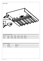
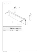
Страница 28: ...2400003 Maintenance pin 3 65025055 Stud bolt 4 1005 11 00 03 Ball knob Table A 1 Decks 1 thread plate Width Length XPH 20 XPH 22 XPH 25 XPH 28 XPH 30 XPH 35 XPH 20 07204100 07214100 07224100 07234100 07244100 07254100 XPH 21 07206100 07216100 07226100 07236100 07246100 07256100 XPH 22 07208100 07218100 07228100 07238100 07248100 07258100 ...

Страница 29: ...PH 25 XPH 28 XPH 30 XPH 35 Side beam Left 9 07100210 07110210 07120210 07130210 07140210 06150210 Side beam Right 2 07100215 07110215 07120215 07130215 07140215 06150215 Vert support 14 06100240 06100240 06100240 06100240 06100240 06150240 Table B 3 Additional parts Index Reference Description 3 65012448 Socket head screw 4 65055021 Washer 5 65050136 Hex nut 6 65002457 Hex head screw 7 02400006 Gu...

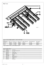
Страница 30: ...046 Rubber buffer CTL 12 65051034 Self locking nut 13 65055019 Washer 14 07200309 Safety hook Table C 1 Lip with standard clearance C 240 mm thread plate Lip 1 Guide roller front 2 Guide roller rear 3 Slide plate 4 Width Length 06 08 10 XPH 20 07204300 07214300 07224300 02400004 02400005 02400002 XPH 21 07206300 07216300 07226300 02400004 02400005 02400002 XPH 22 072008300 07218300 07228300 024000...

Страница 31: ... T slot nut 18 65225004 Socket head screw Table C 3 Lip with standard clearance C 240 mm and sections thread plate Lip 1 Guide roller front 2 Guide roller rear 3 Slide plate 4 Width 06 08 10 XPH 22 07208325 07218325 07228325 02400005 02400005 02400002 Section 19 02663200 02673200 02673200 Only for models 20 and 22 Not for models 20 and 22 Fig C 2 2 ...

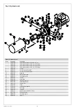
Страница 32: ...assy 230V 60 HZ Option 2 02606602 O Ring 8 68308013 2 2 Cartr valve CEI D DT 9 68308014 2 2 Cartr valve NC BI DIR 10 69481501 Solenoid 11 32006257 Main release valve 12 68208501 Lip release valve 13 68238501 Throttle 14 02335636 Logic valve 16 02600699 Plug incl pos 15 20 68113020 Hydr pump 50 Hz 21 68821301 Suction filter 23 02606623 Tank 24 02335614 Filler breather dipstick 25 02335623 Drain plu...

Страница 33: ...afety valve 5 02406001 Hydr hose main cylinder 6 see Table E 1 Main cylinder incl 3 and 4 7 01510021 Hinge pin frame side Fig F Lip cylinder Fig F Lipcilinder Fig F Lippenzylinder Fig F Cylindre à lèvre Table F 1 Lip cylinder Index Reference Description 1 02406200 Lip cylinder lip length 06 02416200 Lip cylinder lip length 08 10 2 02400008 Shock absorber 3 65055422 Washer 4 65051034 Locking nut 5 ...

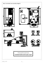
Страница 34: ...eningskast en aansluitschema Fig G Schaltkasten und und Anschlussplan Fig G Boîtier de commande et schéma de racc ord ement Picture may differ from actual design For spare parts and additional information refer to the manual of the SSC SMC control box which is available on request ...

Страница 35: ...ydraulic diagram Index Reference 1 Main cylinder 2 Lip cylinder 3 Stop valve 4 Shuttle valve 5 Directional valve 6 Directional valve 7 Pressure relief valve 8 Pressure relief valve lip cylinder 9 Pressure switch A Connection port 1 4 BSP B Connection port 1 4 BSP C Connection port 1 4 BSP PS Connection port 1 4 BSP P1 Measuring port 1 8 BSP ...

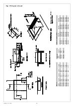
Страница 36: ...2065 2260 2565 2870 3065 3565 Length XPH 20 XPH 22 XPH 25 XPH 28 XPH 30 XPH 35 Fig I Croquis de la fosse fermé Table I 2 A mm 2030 2140 2280 Width XPH 20 XPH 21 XPH 22 Table I 3 Curb angle set XPH 22 06108950 06118950 06128950 06138950 06148950 06158950 XPH 21 06106950 06116950 06126950 06136950 06146950 06156950 XPH 20 06104950 06114950 06124950 06134950 06144950 06154950 XPH 20 XPH 22 XPH 25 XPH...

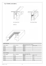
Страница 37: ...2014 37 Fig J Slab Option Fig J Afdichting voorzijde Optie Fig J Vorhang Option Fig J Bavette Option Table J 1 Slab Type Reference XPH20 XPH30 XPH35 XPH 20 06204910 06254910 XPH 21 06206910 06256910 XPH 22 06208910 06258910 ...

Страница 38: ...100925 66201087 2 x 3m XPH 22 06110925 66201087 2 x 3m XPH 25 06120925 66201087 2 x 3m XPH 28 06130925 66201087 2 x 3m XPH 30 06140925 66201087 2 x 3m XPH 35 06150925 66201087 2 x 4 5m Table K 2 Brushes Type dockleveller Brush set reference Replacement brush 26 mm x 1000 mm Reference Number required XPH 20 06100920 02219912 4 XPH 22 06110920 02219912 5 XPH 25 06120920 02219912 5 XPH 28 06130920 02...

Страница 39: ...Stertil B V P O Box 23 9288 ZG Kootstertille The Netherlands Tel 31 0 512 334444 Fax 31 0 512 332099 E mail dp stertil nl Internet www stertil nl ...

Отзывы: