Digital Microstep Driver DM556N
7
(4). t4: Low level width is not less than 2.5µs.
3.5 Wiring Requirements
(1). In order to prevent the driver from being disturbed, it is recommended to use a twisted-pair
shielded cable and the shield layer grounded (single-ended ground). Make sure the connection is
true ground, otherwise the interference may be more serious.
(2). The control signal lines and the motor lines are not allowed to be side by side, preferably
separated by at least 10 cm. Otherwise, the motor electromagnetic noise easily interfere with the
control signal, causing the motor to be inaccurately positioned and the system is unstable.
(3). If one power supply is used for multiple drivers, parallel mode should be used at the power
supply, and it is not allowed to connect to another driver at the driver’s pin.
(4). It is strictly forbidden to plug and unplug the driver motor line terminal. When the energized
motor stops, there is still a large current flowing through the coil. Pulling out the motor line
terminal will cause a huge instantaneous induced electromotive force to burn the driver.
(5). It is strictly forbidden to add tin to the wire lead and then connect the terminal. Otherwise, the
terminal may be damaged due to the contact resistance becoming large and overheating.
4. DIP Switch Setting
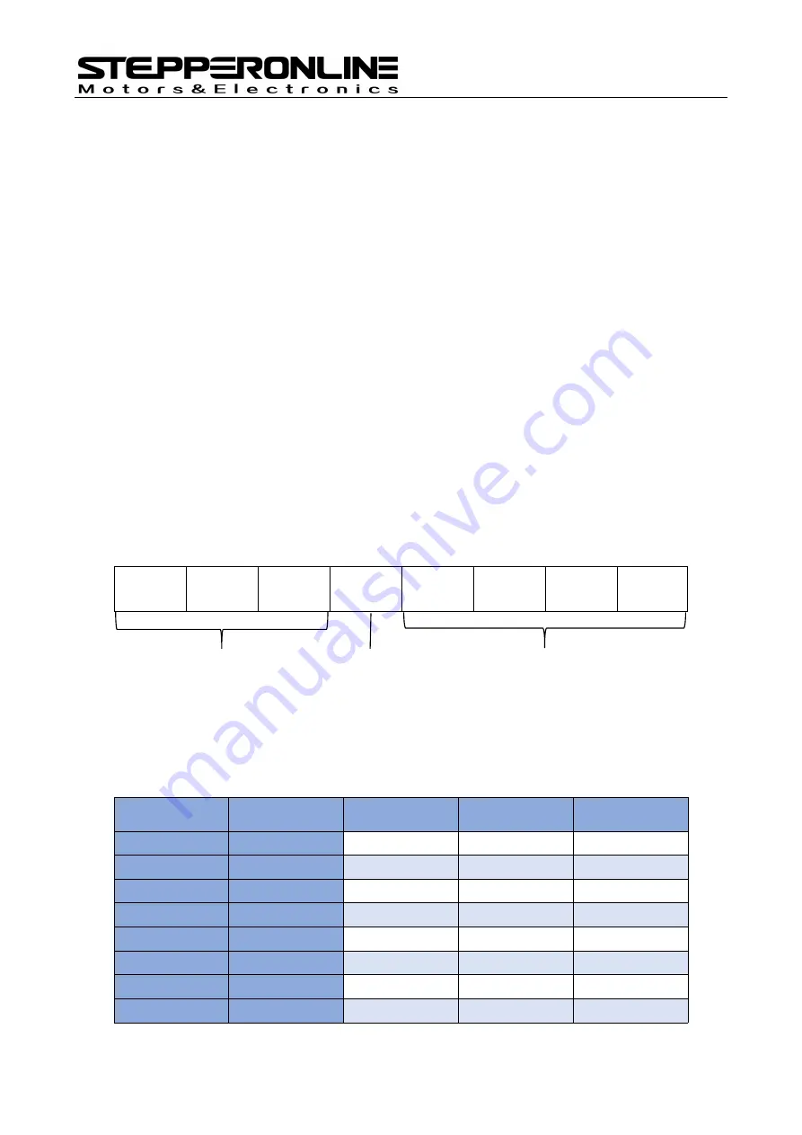
The DM556N driver uses a 8-bit DIP switch to set operating current, standstill current, and
microstep resolution. The detailed description is as follows:
SW1
SW2
SW3
SW4
SW5
SW6
SW7
SW8
Figure 5: DIP switch setting
4.1 Operating Current Setting
The first three bits (SW1, SW2, SW3) of the DIP switches are used to set the operating current of the
motor. Select the setting that is closest value to the motor as required current.
Peak Current RMS Current
SW1
SW2
SW3
1.4A
1.0A
ON
ON
ON
2.1A
1.5A
OFF
ON
ON
2.7A
1.9A
ON
OFF
ON
3.2A
2.3A
OFF
OFF
ON
3.8A
2.7A
ON
ON
OFF
4.3A
3.0A
OFF
ON
OFF
4.9A
3.5A
ON
OFF
OFF
5.6A
4.0A
OFF
OFF
OFF
Operating current
Standstill current
Microstep resolution


