


Instruction Manual of
-S3 Inverter for Elevator
B-
13
List
s of
Function Parameters
, Runnin
g
-st
atus and Fault
s
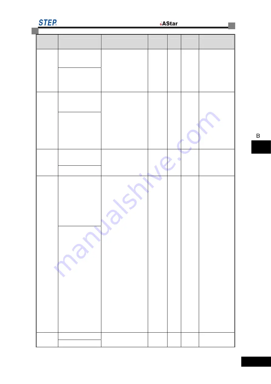
Function
Code
Name
Content
Range
Unit
Default
Remarks
输出电流异常确认
K31
Surge Cur Times
Occurrences of abnormal
current output
B11 < 60000: normal
protection
B11 >= 60000: protection
disabled
0
~
65535
次
5000
数字速度切换模式
K32
Digi Ref Mode
With the speed given
through digital signals,
whether the speed may
be switched
=0: acceleration not
allowed during
deceleration
=1: any switching allowed
0/1 ×
1
过调制功能
K33
Overshoot Enable
Overshoot
=0: disabled
=1: enabled
0/1 ×
0
保护功能是否有效
K34
Protect Action
Protection
bit0
=
0: software
over-current (27) enabled
bit0
=
1: software
over-current (27) disabled
bit1
=
0: the Inverter will
automatically cancel the
fault signal when the
voltage reaches specific
level
bit1
=
1: the Inverter will
not cancel any fault
signal of under voltage
bit2
=
0: wrong phase
sequence of c and d of
1387 encoder (28)
enabled
bit2
=
1: wrong phase
sequence of c and d of
1387 encoder (28)
disabled
0
~
65535
× 0
输出缺相故障确认
K35
Output Loss time
Confirmation time of
output phase loss
0
~
20000
ms 5000
Содержание iAStar-S3
Страница 1: ......
Страница 2: ......
Страница 18: ......
Страница 26: ......
Страница 32: ......
Страница 86: ......
Страница 124: ......
Страница 127: ...Instruction Manual of S3 Inverter for Elevator Figure 7 1 Internal control of the Inverter Application of Elevator 7 3 ...
Страница 163: ...Instruction Manual of S3 Inverter for Elevator pection Fault Ins 8 5 ...
Страница 164: ...Shanghai STEP Electric corporation The motor runs without speed variation pection Fault Ins 8 6 ...
Страница 168: ......
Страница 196: ......
Страница 198: ......
Страница 200: ......


