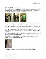
Installation G
Solar Tube Company - Eco Airpump
www.ecoairpump.co.uk
Support Line: 08444 930099
11
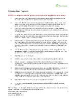
Filling the Resol Flowcon S
NOTE! To be carried out when the system is cold or prior to the installation of the heat pipes
1.
Connect the brass hose adaptors to the fill connector (top on right hand side) and to the
drain/flush connector (bottom on right hand side beside flowmeter)
2.
Connect the fluid (Tyfocor or similar) supply hose to the fill connector and open the valve
beside it. The fluid supply hose can come from a Resol Proficenter pump, PAW canister
pump, central-heating filling pump or a good quality pump-up garden sprayer.
3.
Connect the drain/flush hose to the drain/flush connector and open the valve beside it.
Ensure the end of the hose lies in a container to capture the fluid, which will come out during
the filling process.
4.
Close the ball valve at the top of the flowmeter by turning the slot of the screw to a horizontal
position. Open the non-return valve (immediately above the pump) by using a 14mm spanner
to turn the valve 45
(from 12 o’clock to 1h30m).
5.
Pump fluid into the system through the supply hose. Keep pumping after it comes out of the
drain/flush hose until the fluid being released no longer has any bubbles in it. Fluid can be
transferred from the drain/flush container to the pump container periodically. Typically, flush
through the system for 15 minutes. It is necessary to open the valve on the flowmeter from
time to time.
6.
Increase the pressure (on the pump station gauge) as much as the pump will allow
to a
maximum of 6 Bar
by closing the drain/flush valve and pumping in some more fluid. If the
pressure drops then there is a leak in the system.
7.
Open the valve on the flowmeter.
8.
Vent the pump using the screw in the middle of it (use large flat headed screwdriver).
9.
Reduce pressure by releasing a little fluid from the drain/flush valve to the collector
manufacturer’s recommended operating pressure (typically 1.25 Bar when system is cold for
STC collectors).
10.
Run pump at 100% speed (using manual control
– see controller instructions) for about 15
minutes. Stop pump and open manual bleed valve to release any remaining air.
11.
Restart pump via controller at 100%. Adjust speed by turning black knob on pump (I, II, III) so
that reading on lower edge of float in flowmeter reading is the same or slightly higher than
collector optimum speed (0.1L/min for STC collectors, e.g. 2L/min for each 20 tube collector).
The flow rate can be adjusted via the valve on the flowmeter.
12.
Open the ball valve above the pump by turning it back to 12 o’clock.
13.
Fit the front insulation jacket to the pump station and switch the controller to automatic
operation.
NB. The Flowcon S can usually be bled by releasing air from the pump and manual air separator. Some
systems may need to be manually bled at their highest point.


