background image

Installation G 

Solar Tube Company - Eco Airpump 
www.ecoairpump.co.uk 
Support Line: 08444 930099 

10 

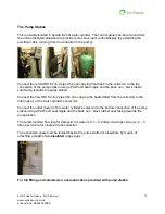
The Pump Station 


This is usually located in beside the hot water cylinder. The control panel can be removed from 
the unit and located elsewhere to provide more convenient control/display (by extending the 
electrical cable running from the controller to the pump). 


Connect the return DN16 2-in-2 pipe (the one carrying fluid back to the collector) to the top 
connection of the pump station using a PAW self seal nipple and the back nut 

– black rubber 

seal facing towards the pump station.  
 
Connect the flow DN16 2-in-2 pipe (the one carrying the heated fluid from the collector) to the 
inlet (upper) of the water cylinder’s solar coil. 
 
Connect the outlet (lower) of the water cylind

er’s solar coil to the bottom connection of the pump 

station using a PAW self seal nipple and the back nut 

– black rubber seal facing towards the 

pump station.  
 
The recommended flow rate for domestic hot water is 0.1 

– 0.2 litres/minute per tube (i.e. 2 – 3 

litres per minute for single 20 tube collector). 
 
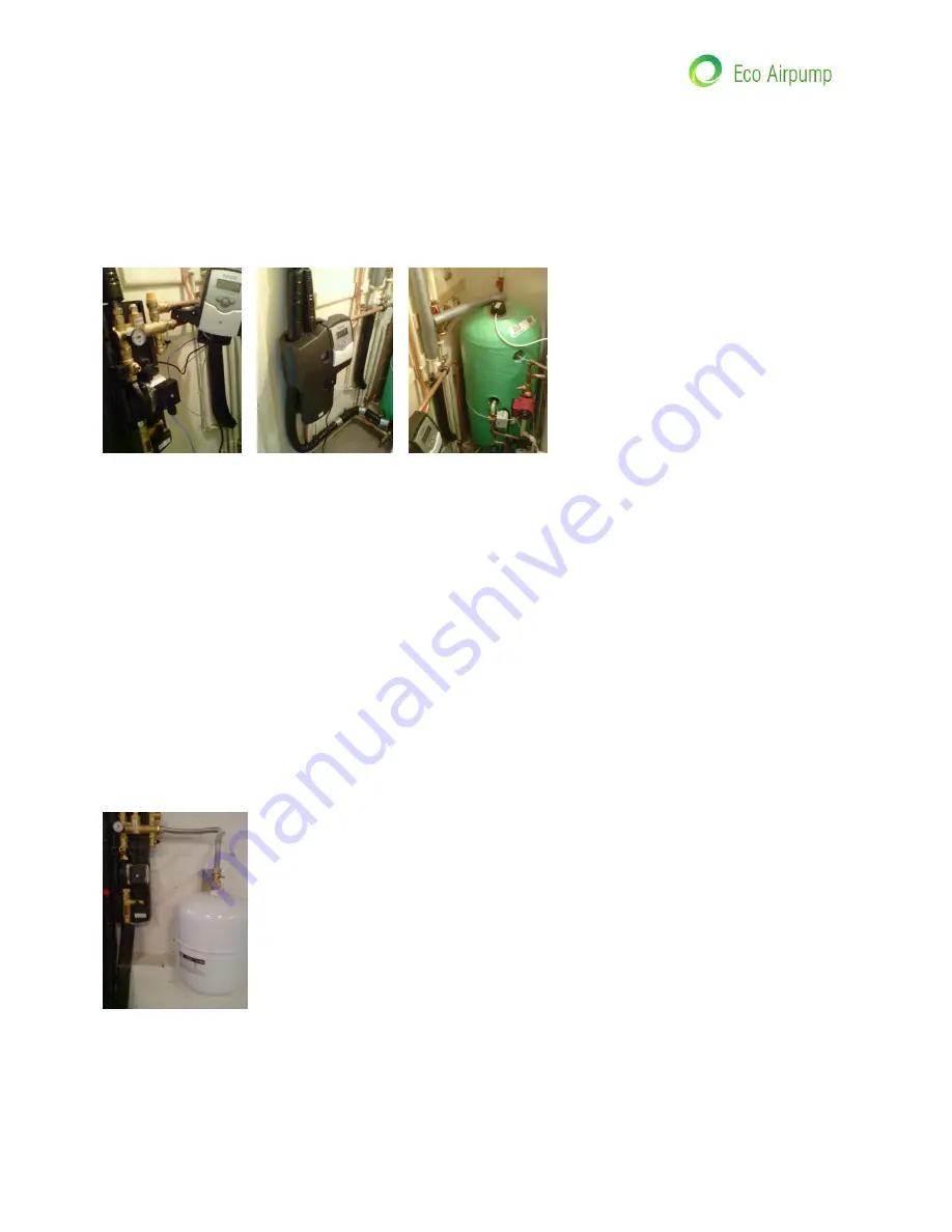
The expansion vessel can be located beside the pump station or elsewhere by means of 
attaching a length of 

un-insulated

 copper pipe. 


For full fitting and commission, see instructions provided with pump station. 


Содержание Solar SPA Collector Kit

Страница 1: ...any persons working with you are competent to do so and only after you have assessed all risks and either eliminated them or reduced them to safe levels Caution There is a boiling risk which is fully...

Страница 2: ...are here to help so please let us know if you are having problems or require some more clarification Just in case you need reminding why you chose a STC System here are the key features of our kits 1...

Страница 3: ...models will perform well even when not pointing due south However it will be necessary to increase the number of tubes over what would be expected for a due south installation Position Allow extra eva...

Страница 4: ...frame vertical pieces to back of manifold 2 Turn over 3 Attach cross rail so that opened groove is at top 4 Secure cross rails using M13 bolts and stainless fittings 5 The collector can now be offere...

Страница 5: ...lts 2 Attach feet folding in tabs to fit M10 X 45 bolts 3 Attach side supports M13 x 20 bolts 4 Attach rear supports M13 x 20 bolts 5 Join rear supports at middle of X M10 x 30 bolt 6 The collector ca...

Страница 6: ...s to line up with the holes that are not in line with the rafters you will see the holes very clearly 3 Back on the roof drill pilot holes into the wood drilling through your holes in the tiles using...

Страница 7: ...mm brass fittings or 22mm T brass fittings if an external air vent is fitted In all cases a hole must be cut in the tiles at each end of the collector or at each end of a multiple collector array The...

Страница 8: ...t is attached to the fitting WITHOUT the washer and tightened this creates a flange on the end of the pipe 4 Unscrew the fitting insert the washer reconnect the fitting and tighten The compression fit...

Страница 9: ...emperature sensor provided with the controller from the pump station box smear some heat transfer paste from the tube in the small white box found in the collector frame box onto the metal sensor tube...

Страница 10: ...rubber seal facing towards the pump station Connect the flow DN16 2 in 2 pipe the one carrying the heated fluid from the collector to the inlet upper of the water cylinder s solar coil Connect the out...

Страница 11: ...ner periodically Typically flush through the system for 15 minutes It is necessary to open the valve on the flowmeter from time to time 6 Increase the pressure on the pump station gauge as much as the...

Страница 12: ...tips of the heat pipes Next Put rubber end caps on tube it is often easier to wipe a little washing up liquid around the top and the bottom ends of the glass tubes to ease fitting Push copper tip of...

Отзывы: